
Bend Allowance for Sheet Metal: Complete Guide to Accurate Flat Pattern Calculations
Sheet metal fabrication requires more than simply cutting and bending metal. One of the most important factors affecting dimensional accuracy is bend allowance (BA). Every bend stretches the outer surface of the material while compressing the inner surface. If designers ignore this material deformation, the finished part may be several millimeters longer or shorter than intended, leading to assembly problems, excessive scrap, and unnecessary production costs.
Modern CNC laser cutting, press brake forming, aerospace manufacturing, automotive production, electrical enclosures, and industrial equipment all rely on accurate bend allowance calculations to produce precise flat patterns. Although most CAD software can calculate bend allowance automatically, understanding the underlying principles remains essential for engineers, designers, and manufacturers.
This guide explains how bend allowance works, how it relates to K-Factor and bend deduction, and how manufacturers calculate accurate flat lengths for production.
What Is Bend Allowance?
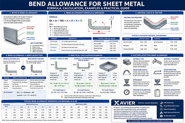
Bend allowance is the length of material that occupies the curved section of a bend. Instead of measuring the outside or inside arc, bend allowance measures the length along the neutral axis, the only layer within the material that neither stretches nor compresses during bending.
Without bend allowance, flat pattern dimensions would always be incorrect because sheet metal changes shape during forming.
For example, imagine producing an electronic enclosure with four 90° bends.
If every bend introduces approximately 2.3 mm of additional material length, ignoring bend allowance could create a total dimensional error approaching 9 mm, enough to prevent proper assembly.
Why Bend Allowance Matters
Accurate bend allowance helps manufacturers:
- Produce correct flat blank dimensions
- Reduce scrap rates
- Improve assembly accuracy
- Maintain tighter production tolerances
- Minimize trial-and-error adjustments
- Improve repeatability across production batches
In high-volume manufacturing, even a 0.2 mm error per bend can become a significant quality issue after thousands of parts are produced.
Material Behavior During Bending
When sheet metal is bent, three different deformation zones appear.
| Material Layer | What Happens |
|---|---|
| Outside Surface | Stretches under tension |
| Neutral Axis | No length change |
| Inside Surface | Compresses under pressure |
The neutral axis is not located exactly in the middle of the sheet. Instead, it shifts toward the inside radius depending on:
- Material type
- Thickness
- Bend radius
- Forming method
- Tooling
- K-Factor
This shifting neutral axis is the primary reason bend allowance calculations require more than simple geometry.
Typical Applications
Almost every fabricated sheet metal product depends on bend allowance.
Examples include:
| Industry | Typical Parts |
|---|---|
| Automotive | Brackets, chassis components |
| Aerospace | Structural panels |
| Electronics | Server cabinets, electrical enclosures |
| Medical | Equipment housings |
| Construction | HVAC ducts |
| Industrial Equipment | Machine covers, mounting plates |
Whether manufacturing one prototype or one million parts, accurate bend allowance directly affects production quality.
Bend Allowance Formula and Variables
The standard bend allowance equation used throughout the sheet metal industry is:
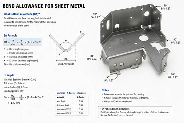
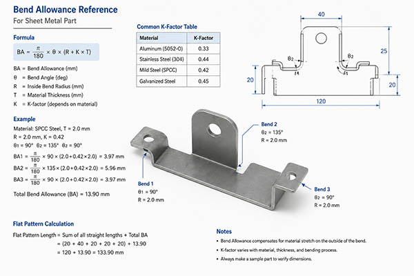
BA = (π ÷ 180) × A × (R + K × T)
Where:
| Symbol | Meaning |
|---|---|
| BA | Bend Allowance |
| A | Bend Angle (degrees) |
| R | Inside Bend Radius |
| T | Material Thickness |
| K | K-Factor |
Although the equation appears simple, each variable significantly influences the final flat pattern.
Bend Angle (A)
The bend angle determines how much of the material becomes curved.
Typical examples include:
| Bend Angle | Common Application |
|---|---|
| 30° | Light brackets |
| 45° | Reinforcement flanges |
| 90° | Boxes and enclosures |
| 120° | Structural components |
| 180° | Hem bends |
As the bend angle increases, bend allowance increases proportionally because more material forms the curved section.
Material Thickness (T)
Thicker material generally results in larger bend allowances because more material must deform during bending.
Example:
| Thickness | Relative Bend Allowance |
|---|---|
| 1 mm | Small |
| 2 mm | Medium |
| 3 mm | Large |
| 5 mm | Very Large |
However, thickness alone does not determine bend allowance.
A thicker sheet combined with a larger inside radius may produce similar results to a thinner sheet with a sharper bend.
Inside Bend Radius (R)
Inside radius is another critical variable.
Small radii create:
- Higher material strain
- Greater springback
- Increased cracking risk
- Greater sensitivity to K-Factor
Larger radii generally:
- Reduce material stress
- Improve bend consistency
- Lower cracking probability
- Produce more predictable bend allowance values
Many manufacturers follow a minimum inside radius approximately equal to the material thickness for mild steel, although actual recommendations depend on material properties and forming methods.
K-Factor
Among all variables, the K-Factor introduces the greatest uncertainty.
It determines where the neutral axis lies inside the sheet thickness.
Typical values include:
| Forming Method | Typical K-Factor |
|---|---|
| Sharp Air Bend | 0.30–0.35 |
| Standard Air Bend | 0.38–0.45 |
| Bottom Bending | Around 0.42 |
| Coining | Up to 0.50 |
These values are starting points only. Most experienced fabrication shops establish their own bend tables through trial bends and production validation because material properties, tooling, coatings, and press brake conditions all influence the effective K-factor.
Example Calculation
Suppose we have:
- Material thickness = 2 mm
- Inside radius = 2 mm
- Bend angle = 90°
- K-Factor = 0.40
Substituting these values into the standard formula gives a bend allowance of approximately 3.77 mm.
This means the curved portion of the bend contributes about 3.77 mm to the total flat pattern length. Using an incorrect K-factor or bend radius would alter this value and could lead to noticeable dimensional errors in the finished component, especially when multiple bends are involved.
K-Factor and the Neutral Axis: The Foundation of Accurate Bend Allowance
Many engineers consider the K-Factor to be the most influential variable in bend allowance calculations because it determines where the neutral axis is located inside the sheet thickness. Even if the bend angle, inside radius, and material thickness remain constant, changing the K-Factor will change the calculated flat pattern length.
Understanding how the neutral axis behaves during bending helps manufacturers reduce dimensional errors, improve first-pass yield, and eliminate repeated press brake adjustments.
What Is the Neutral Axis?
When sheet metal is bent, the material experiences three different zones of deformation:
- Outer surface: Under tensile stress, causing elongation.
- Inner surface: Under compressive stress, causing shortening.
- Neutral axis: Experiences almost no change in length.
The neutral axis is an imaginary layer where the material neither stretches nor compresses. Bend allowance is always measured along this layer because it represents the true length of the material after deformation.
If the neutral axis were located exactly at the center of the sheet, bend calculations would be relatively simple. However, during real-world bending, the neutral axis shifts toward the inside radius, and the amount of this shift depends on multiple factors.
Why the Neutral Axis Moves
The position of the neutral axis changes because metal does not deform uniformly. As bending force increases, the outer fibers stretch more than the inner fibers compress.
Several factors influence this movement:
| Factor | Influence on Neutral Axis |
|---|---|
| Material type | High-strength materials shift differently than softer alloys |
| Material thickness | Thicker sheets generally create larger neutral axis movement |
| Inside bend radius | Smaller radii push the neutral axis inward |
| Bending method | Air bending, bottoming, and coining produce different positions |
| Tool geometry | Punch and die dimensions affect deformation |
| Material temper | Harder materials exhibit different strain characteristics |
For example:
- A 1 mm aluminum sheet bent with a large radius may have a K-Factor close to 0.45.
- A 3 mm stainless steel sheet bent with a sharp radius may have a K-Factor around 0.32.
Although these values appear close numerically, they can produce several millimeters of difference across a complex part containing multiple bends.
Understanding the K-Factor
The K-Factor describes the position of the neutral axis relative to the material thickness.
It is defined as:
K = t / T
Where:
| Symbol | Meaning |
|---|---|
| t | Distance from the inside surface to the neutral axis |
| T | Material thickness |
A K-Factor of:
- 0.50 means the neutral axis is exactly at the center.
- 0.40 means it has shifted toward the inside.
- 0.30 indicates an even greater inward shift.
Since most sheet metal bends cause inward movement of the neutral axis, practical K-Factor values generally range between 0.30 and 0.50.
Typical K-Factor Values by Material
Different metals respond differently during bending because of variations in ductility, yield strength, and work hardening.
| Material | Typical K-Factor |
|---|---|
| Aluminum 5052 | 0.33–0.45 |
| Mild Steel | 0.35–0.45 |
| Stainless Steel 304 | 0.30–0.42 |
| Galvanized Steel | 0.35–0.44 |
| Brass | 0.36–0.45 |
| Copper | 0.38–0.46 |
These ranges are only starting points.
Professional fabrication shops rarely rely solely on handbook values. Instead, they perform test bends and create material-specific bend tables for each combination of:
- Material supplier
- Material thickness
- Tooling
- Press brake
- Die opening
- Punch radius
This approach produces significantly higher dimensional accuracy than using generic K-Factor values.
How Press Brake Methods Affect K-Factor
Different bending methods change how much the material deforms.
| Bending Method | Typical Characteristics | Typical K-Factor |
|---|---|---|
| Air Bending | Least contact with die | 0.30–0.45 |
| Bottom Bending | Material fully contacts die | 0.38–0.45 |
| Coining | Material heavily compressed | 0.45–0.50 |
Air Bending
The punch does not force the sheet completely into the die.
Advantages include:
- Lower forming force
- Longer tool life
- Flexible angle adjustment
- Most common production method
Because the material experiences less compression, K-Factor values tend to vary more.
Bottom Bending
The sheet fully contacts the die.
Advantages include:
- Better repeatability
- Improved angle consistency
- Reduced springback
Since deformation is more controlled, bend allowance calculations become more predictable.
Coining
Coining applies extremely high pressure that plastically deforms the entire bend area.
Advantages include:
- Minimal springback
- Excellent dimensional accuracy
- Very consistent bend geometry
Disadvantages include:
- High machine tonnage
- Increased tooling wear
- Higher production cost
Coining is generally reserved for precision applications rather than high-volume production.
Why Manufacturers Build Their Own Bend Tables
Even when using the same alloy and thickness, two manufacturers may obtain different bend allowance values.
Reasons include:
- Different material suppliers
- Different rolling directions
- Different press brake brands
- Different die openings
- Different punch radii
- Different lubrication conditions
- Different machine calibration
For example:
| Shop | Material | Thickness | Measured BA |
|---|---|---|---|
| Factory A | 304 Stainless | 2 mm | 3.74 mm |
| Factory B | 304 Stainless | 2 mm | 3.83 mm |
| Factory C | 304 Stainless | 2 mm | 3.69 mm |
Although all three values are technically correct for their specific processes, using another factory’s bend table could introduce measurable errors.
This is why experienced sheet metal manufacturers continually update their bend databases based on actual production data instead of relying exclusively on theoretical calculations.
Bend Allowance vs. Bend Deduction
One of the most common sources of confusion in sheet metal design is the difference between Bend Allowance (BA) and Bend Deduction (BD). While both are used to determine flat pattern dimensions, they represent different concepts and are applied differently in calculations.
Choosing the wrong method can result in inaccurate blank sizes, poor fit-up during assembly, and increased material waste.
What Is Bend Deduction?
Bend Deduction is the amount subtracted from the total length of the two outside flange dimensions to determine the correct flat pattern length.
Unlike Bend Allowance, which measures the material length along the neutral axis, Bend Deduction accounts for the geometric relationship between the bent flanges and the material consumed during forming.
The simplified relationship is:
Flat Length = Flange A + Flange B − Bend Deduction
This method is commonly used in manufacturing drawings because flange dimensions are usually specified as outside dimensions.
Key Differences Between Bend Allowance and Bend Deduction
| Feature | Bend Allowance | Bend Deduction |
|---|---|---|
| Purpose | Calculates arc length along the neutral axis | Calculates material to subtract from flange lengths |
| Used In | Engineering calculations, CAD software | Production drawings, shop floor calculations |
| Based On | Neutral axis length | Outside dimensions |
| Depends On | K-Factor, bend radius, thickness, angle | Bend allowance plus geometric relationships |
| Common Users | Design engineers | Fabricators and machine operators |
Although they serve different purposes, both methods produce the same final flat pattern when calculated correctly.
Example Comparison
Consider a sheet metal bracket with:
- Flange A = 50 mm
- Flange B = 40 mm
- Material thickness = 2 mm
- Inside bend radius = 2 mm
- Bend angle = 90°
Using the Bend Allowance method, the flat pattern is calculated by adding the straight sections and the bend allowance measured along the neutral axis.
Using the Bend Deduction method, the outside flange dimensions are added together first, and then the bend deduction value is subtracted.
Both methods arrive at the same final blank length, provided the underlying bend data (K-Factor, radius, thickness, and angle) is accurate.
Which Method Should You Use?
The answer depends on your workflow.
Use Bend Allowance when:
- Creating CAD models
- Building sheet metal design libraries
- Developing bend tables
- Performing engineering calculations
- Optimizing CNC programming
Use Bend Deduction when:
- Reading fabrication drawings
- Calculating flat blanks manually
- Communicating flange dimensions with operators
- Preparing production documentation
Most modern CAD/CAM systems automatically convert between Bend Allowance and Bend Deduction in the background, allowing engineers to work with whichever method best suits their design process.
Practical Bend Allowance Calculation Examples
Although bend allowance formulas are straightforward, applying them correctly in real manufacturing scenarios requires attention to material properties, tooling, and dimensional references. The following examples demonstrate how engineers and fabricators calculate flat pattern dimensions for common sheet metal components.
Example 1: Single 90° Bend
Suppose a simple L-shaped bracket has the following specifications:
| Parameter | Value |
|---|---|
| Material | Mild Steel |
| Thickness | 2.0 mm |
| Inside Bend Radius | 2.0 mm |
| Bend Angle | 90° |
| K-Factor | 0.40 |
| Flange A | 50 mm |
| Flange B | 40 mm |
The bend allowance formula is:
BA = (π ÷ 180) × A × (R + K × T)
Substituting the values:
- Bend angle = 90°
- Radius = 2 mm
- Thickness = 2 mm
- K-Factor = 0.40
The bend allowance is approximately:
BA ≈ 3.77 mm
The flat pattern length becomes:
50 + 40 + 3.77 − Setback Adjustments
Depending on the design reference (inside, outside, or tangent dimensions), CAD software will automatically apply the required setback or bend deduction values to produce the final blank length.
Example 2: U-Shaped Bracket with Two Bends
Now consider a U-shaped component used for mounting electronic equipment.
| Parameter | Value |
|---|---|
| Material | Stainless Steel 304 |
| Thickness | 1.5 mm |
| Radius | 1.5 mm |
| Bend Angle | 90° × 2 |
| Side Flanges | 30 mm |
| Base Width | 80 mm |
| K-Factor | 0.38 |
Each bend contributes its own bend allowance.
Approximate calculation:
- Bend Allowance per bend ≈ 2.65 mm
- Two bends ≈ 5.30 mm
Ignoring bend allowance would shorten the finished part by more than 5 mm, causing alignment problems when installing fasteners or assembling mating components.
Example 3: Four-Bend Electrical Enclosure
Electrical cabinets often include multiple bends on all four sides.
Specifications:
| Parameter | Value |
|---|---|
| Material | Galvanized Steel |
| Thickness | 1.2 mm |
| Radius | 1.2 mm |
| Number of Bends | 4 |
| Bend Angle | 90° |
If each bend contributes approximately 2.2 mm of bend allowance:
| Number of Bends | Total Bend Allowance |
|---|---|
| 1 | 2.2 mm |
| 2 | 4.4 mm |
| 3 | 6.6 mm |
| 4 | 8.8 mm |
An error of only 0.3 mm per bend accumulates to over 1 mm across the enclosure, which can affect door alignment, panel fit, or hole positioning.
Multi-Bend Tolerance Stack-Up
As the number of bends increases, dimensional errors accumulate.
| Number of Bends | Error per Bend | Total Error |
|---|---|---|
| 2 | 0.20 mm | 0.40 mm |
| 4 | 0.20 mm | 0.80 mm |
| 6 | 0.20 mm | 1.20 mm |
| 10 | 0.20 mm | 2.00 mm |
This phenomenon is known as tolerance stack-up.
For products such as:
- Server racks
- Aerospace brackets
- Medical equipment
- Battery enclosures
- Precision machine covers
Even a cumulative error of 1 mm may exceed design tolerances.
Therefore, experienced manufacturers verify bend allowance through trial bends before full-scale production.
Manual Calculation vs. CAD Software
Modern CAD systems can automatically calculate bend allowance using built-in sheet metal modules.
| Method | Advantages | Limitations |
|---|---|---|
| Manual Calculation | Easy to understand, suitable for simple parts | Time-consuming and prone to calculation errors |
| CAD Software | Fast, accurate, ideal for complex geometries | Requires correct bend tables and K-Factor settings |
Popular CAD platforms such as SolidWorks, Autodesk Inventor, and Siemens NX allow users to define custom bend tables based on actual production data. This ensures that flat patterns generated by the software match the capabilities of the fabrication shop.
Manufacturing Factors That Affect Bend Allowance
While formulas provide the theoretical basis for bend allowance, actual manufacturing conditions introduce variations that can significantly influence the final dimensions of a bent part. Understanding these variables helps engineers improve design accuracy and reduce costly trial-and-error adjustments.
Material Type
Different metals exhibit different mechanical properties, including yield strength, ductility, and work hardening behavior. These characteristics affect how the material stretches and compresses during bending.
| Material | Formability | Typical Influence |
|---|---|---|
| Aluminum | Excellent | Lower bending force, stable bend allowance |
| Mild Steel | Good | Predictable forming behavior |
| Stainless Steel | Moderate | Higher springback, greater forming force |
| Copper | Excellent | Easily formed, low springback |
| Brass | Good | Smooth bends but limited fatigue resistance |
| Titanium | Difficult | High springback and precise process control required |
For example, bending 304 stainless steel generally requires greater force and exhibits more springback than bending 5052 aluminum, even when both materials have the same thickness.
Material Thickness
Material thickness directly influences the position of the neutral axis and the amount of deformation that occurs during bending.
General trends include:
- Thicker sheets require higher press brake tonnage.
- Larger thickness often increases bend allowance.
- Thicker materials are less forgiving when using small inside radii.
- Very thin sheets may deform or wrinkle if unsupported.
| Thickness | Typical Manufacturing Consideration |
|---|---|
| 0.5 mm | Easy to bend but susceptible to distortion |
| 1.0 mm | Common for electronics enclosures |
| 2.0 mm | Standard industrial fabrication |
| 3.0 mm | Requires increased tonnage |
| 5.0 mm+ | Heavy-duty applications with specialized tooling |
Selecting an appropriate bend radius relative to the sheet thickness is essential for preventing cracking and maintaining dimensional accuracy.
Inside Bend Radius
The inside bend radius influences both the amount of material deformation and the risk of defects.
| Small Radius | Large Radius |
|---|---|
| Higher stress concentration | Lower stress concentration |
| Greater springback | Reduced springback |
| Higher risk of cracking | Improved material flow |
| Increased tooling wear | Longer tool life |
As a general guideline, many fabricators recommend using an inside radius approximately equal to the material thickness for mild steel, although optimal values vary depending on the alloy and forming process.
Grain Direction (Rolling Direction)
Sheet metal is produced through rolling, which creates a grain structure within the material. The orientation of bends relative to this grain affects bend quality.
| Bend Direction | Result |
|---|---|
| Perpendicular to grain | Better ductility, lower cracking risk |
| Parallel to grain | Higher likelihood of cracking, especially with harder materials |
For critical components, engineers often specify bend directions on drawings to ensure consistent forming performance.
Springback
Springback is the elastic recovery that occurs after the bending force is removed. Almost all metals experience some degree of springback.
Factors influencing springback include:
- Material yield strength
- Elastic modulus
- Sheet thickness
- Bend radius
- Forming method
Typical springback behavior:
| Material | Relative Springback |
|---|---|
| Aluminum | Medium |
| Mild Steel | Medium |
| Stainless Steel | High |
| High-Strength Steel | Very High |
| Titanium | Extremely High |
To compensate for springback, manufacturers often overbend the part slightly so that it relaxes to the desired angle after unloading.
Tooling Selection
Punch and die geometry play a critical role in determining bend accuracy.
Key tooling parameters include:
- Punch nose radius
- Die opening width
- Tool material
- Tool wear
- Alignment accuracy
For example, using a die opening that is too narrow can increase forming force and accelerate tool wear, while an excessively wide die opening may reduce bend accuracy and increase dimensional variation.
Regular inspection and maintenance of tooling help maintain consistent bend allowance values throughout long production runs.
Machine Calibration and Process Consistency
Even with accurate calculations, poorly calibrated equipment can introduce dimensional errors.
Important process variables include:
- Press brake ram accuracy
- Backgauge positioning
- Hydraulic pressure consistency
- Tool alignment
- Material positioning repeatability
High-quality manufacturers implement preventive maintenance schedules and perform periodic calibration to ensure repeatable bending performance, especially in industries with tight tolerances such as aerospace, medical devices, and precision electronics.
Best Practices for Improving Bend Accuracy
Manufacturers can improve bend allowance consistency by following these practices:
- Establish material-specific bend tables through trial bends.
- Use consistent tooling for repeat production.
- Verify K-Factor values rather than relying on generic defaults.
- Account for grain direction during part layout.
- Compensate for springback in press brake programming.
- Regularly calibrate forming equipment.
- Validate flat patterns with first-article inspections before full production.
By combining theoretical calculations with empirical production data, manufacturers can achieve high dimensional accuracy, reduce scrap rates, and improve overall fabrication efficiency.
Frequently Asked Questions About Bend Allowance for Sheet Metal
Is Bend Allowance the Same as Bend Deduction?
No. Although the two terms are closely related, they are not interchangeable.
- Bend Allowance (BA) represents the length of material along the neutral axis that forms the bend.
- Bend Deduction (BD) is the value subtracted from the sum of two flange lengths to obtain the correct flat pattern.
Both methods can produce the same final flat length when applied correctly, but they are used in different design and manufacturing workflows.
How Do I Choose the Correct K-Factor?
There is no universal K-Factor suitable for every application.
The appropriate value depends on:
- Material grade
- Material thickness
- Inside bend radius
- Press brake type
- Punch geometry
- Die opening
- Forming method
- Production tolerances
For prototype projects, a typical K-Factor between 0.35 and 0.45 is often used as a starting point. However, for production manufacturing, it is recommended to establish validated bend tables through trial bending and inspection to ensure the highest level of dimensional accuracy.
Does Every Material Have a Different Bend Allowance?
Yes.
Even when thickness and bend angle remain the same, different materials exhibit different mechanical behavior during forming.
For example:
| Material | Relative Bend Allowance Characteristics |
|---|---|
| Aluminum | Excellent formability and predictable bending |
| Mild Steel | Stable and widely used in general fabrication |
| Stainless Steel | Greater springback and higher forming force |
| Copper | High ductility with minimal cracking |
| Titanium | Requires precise process control due to significant springback |
Material properties such as yield strength, elongation, and work hardening all influence bend allowance.
Why Doesn’t My Calculated Bend Allowance Match the Actual Part?
Several factors can cause discrepancies between theoretical calculations and real production results.
Common causes include:
- Incorrect K-Factor selection
- Variation in material batches
- Tool wear
- Incorrect punch or die dimensions
- Machine calibration errors
- Springback compensation
- Differences between air bending and bottom bending
This is why experienced manufacturers verify theoretical values with physical bending tests before mass production.
Can CAD Software Automatically Calculate Bend Allowance?
Yes.
Most modern CAD/CAM platforms include sheet metal design modules capable of automatically calculating flat patterns.
Popular software packages allow users to:
- Define custom bend tables
- Set K-Factor values
- Specify bend deduction
- Simulate bending operations
- Generate manufacturing drawings
- Export CNC-ready flat patterns
However, the software is only as accurate as the input data. Using validated production-specific bend tables is essential for achieving reliable results.
What Is the Most Common Mistake in Bend Allowance Calculations?
One of the most frequent mistakes is relying on generic K-FFactor values without considering actual manufacturing conditions.
Other common errors include:
- Ignoring springback
- Using incorrect inside bend radii
- Mixing inside and outside dimensions
- Applying the wrong bend angle
- Overlooking material grain direction
- Failing to validate calculations with trial bends
Avoiding these mistakes can significantly reduce scrap, improve dimensional consistency, and shorten production lead times.
Conclusion
Accurate bend allowance calculations are fundamental to successful sheet metal fabrication. Whether manufacturing simple brackets or complex multi-bend enclosures, understanding the relationship between bend angle, material thickness, inside radius, neutral axis position, and K-Factor enables engineers to produce precise flat patterns while minimizing waste and rework.
Although mathematical formulas provide an excellent starting point, real-world manufacturing conditions—including material variability, tooling geometry, press brake setup, and springback—must also be considered. For this reason, many leading manufacturers develop customized bend tables based on production testing rather than relying solely on theoretical values.
At Xavier, we combine advanced CNC machining and precision sheet metal fabrication with validated manufacturing processes to deliver consistently accurate components. Our experienced engineering team optimizes bend allowance, tooling selection, and forming parameters for each project, ensuring excellent dimensional accuracy, reliable assembly, and repeatable production quality. Whether you require rapid prototypes or high-volume manufacturing, Xavier provides dependable sheet metal solutions tailored to your exact specifications.
We are an integrated manufacturing and trading company specializing in CNC machining services, mainly providing custom CNC machining and precision machining of various metal parts. We support CNC machining aluminum, CNC machining PEEK, and CNC machining titanium for industries including robotics, aerospace components, marine parts, automotive components, medical parts, and other precision machined parts.
CNC machining aluminum manufacturer, providing high-volume CNC machining PEEK services, contact us for CNC machining titanium prices.
Some of the images and text in this article are collected and compiled from the internet. If there is anything inappropriate, please contact us for processing.