
Industrial Uses of Transmission Gears: Applications, Gear Types, Materials, and Manufacturing Considerations
Transmission gears are among the most important mechanical components used in industrial machinery. Although an electric motor, engine, turbine, or hydraulic drive may generate the original power, gears determine how that power is ultimately delivered to the working equipment.
A transmission gear system can reduce rotational speed, increase output torque, change the direction of rotation, distribute power between multiple shafts, or provide compact speed reduction inside a gearbox. For this reason, gears are found throughout industrial conveyors, mining machines, crushers, mixers, pumps, machine tools, packaging equipment, wind turbines, lifting systems, robotic equipment, and many other power transmission systems.
The industrial use of a gear is not determined simply by its outside diameter or number of teeth. Engineers must consider the complete operating condition, including torque, rotational speed, reduction ratio, shaft arrangement, duty cycle, shock loading, lubrication, operating temperature, accuracy requirements, and expected service life.
For example, a conveyor running continuously for 20 hours per day requires a different gear design from a positioning system that operates intermittently but must repeatedly stop at an exact angular position. Similarly, a worm gear may be appropriate where high reduction and self-locking are important, while a helical or bevel-helical transmission may be a better choice when continuous operation and energy efficiency are the primary requirements.
The following sections explain where industrial transmission gears are used, why different gear designs are selected, and what manufacturing factors determine whether a gear will perform reliably in service.
How Transmission Gears Control Speed, Torque, and Power Flow
At its most basic level, a transmission gear transfers rotational power from one shaft to another through meshing teeth. However, in industrial equipment, the gear system usually performs several functions at the same time.
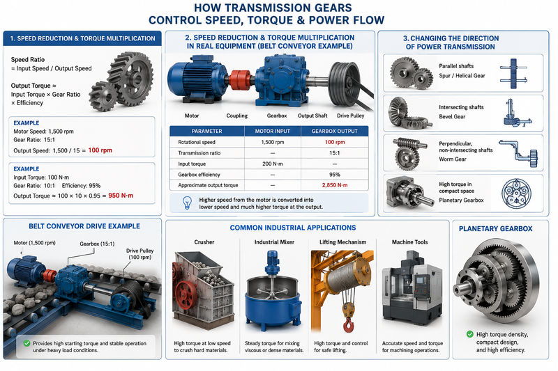
The first major function is speed reduction. Industrial motors frequently operate at speeds that are too high for the final machine. A motor may rotate at approximately 1,500 rpm or 1,800 rpm, while the driven conveyor, mixer, crusher, or lifting drum may require only tens or hundreds of revolutions per minute.
A gear reduction system lowers the output speed according to the transmission ratio:
Speed Ratio = Input Speed / Output Speed
If an electric motor rotates at 1,500 rpm and the gearbox has a 15:1 reduction ratio, the theoretical output speed is:
1,500 / 15 = 100 rpm
The reduction in speed produces a corresponding increase in available output torque, subject to efficiency losses. A simplified relationship is:
Output Torque ≈ Input Torque × Gear Ratio × Efficiency
For example, assume a motor supplies 100 N·m of input torque to a 10:1 gearbox operating at 95% efficiency.
Output Torque ≈ 100 × 10 × 0.95 = 950 N·m
This is why gears are fundamental to heavy industrial machinery. A relatively high-speed motor can be converted into a low-speed, high-torque drive capable of moving heavy material, rotating a loaded drum, crushing rock, or operating a large industrial mixer.
Speed Reduction and Torque Multiplication in Real Equipment
Consider a belt conveyor carrying bulk material.
The motor itself is not connected directly to the conveyor pulley because the motor speed is usually too high and its direct torque may be insufficient for starting the loaded system. Instead, the transmission system may include a motor, coupling, gearbox, output shaft, and drive pulley.
A reduction gearbox changes the motor’s speed into a more useful output condition.
| Parameter | Example Motor Input | Example Gearbox Output |
|---|---|---|
| Rotational speed | 1,500 rpm | 100 rpm |
| Transmission ratio | — | 15:1 |
| Input torque | 200 N·m | — |
| Gearbox efficiency | — | 95% |
| Approximate output torque | — | 2,850 N·m |
The additional torque allows the conveyor to overcome belt friction, material load, pulley resistance, and starting inertia.
This principle is also used in crushers, extruders, rolling mills, agitators, lifting mechanisms, and machine tools. The exact gear arrangement changes from one application to another, but the fundamental objective remains the same: convert the available input power into the speed and torque required by the machine.
Changing the Direction of Power Transmission
Transmission gears are also selected based on shaft orientation.
Parallel shafts can be connected using spur or helical gears. Intersecting shafts are commonly connected using bevel gears. Perpendicular non-intersecting shafts can use worm gear systems.
This becomes important when the physical layout of the machine does not allow the motor and driven component to be installed on the same axis.
For example:
- A standard industrial conveyor gearbox may use parallel-shaft helical gears.
- A right-angle drive for a mixer may use bevel-helical gearing.
- A compact lifting or positioning system may use a worm gear.
- A planetary gearbox may be selected when high torque must be transmitted within a relatively small housing.
The transmission gear therefore affects not only performance but also the mechanical layout of the entire machine.
Industrial Applications of Spur, Helical, Bevel, Worm, and Planetary Gears
Different gear types solve different mechanical problems. Selecting the wrong design can result in excessive heat, noise, bearing loads, premature tooth wear, or unnecessary manufacturing cost.
Spur Gears in General Industrial Machinery
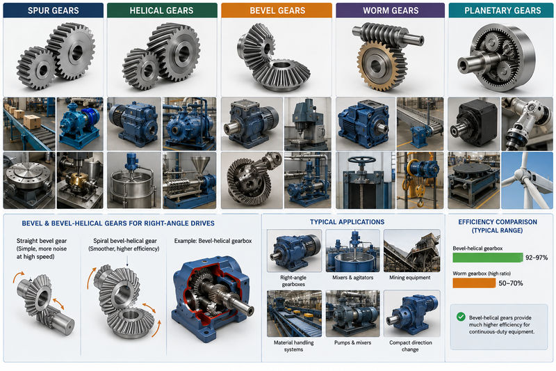
Spur gears have straight teeth parallel to the shaft axis and are normally used to transmit motion between parallel shafts.
Their major advantages include simple geometry, relatively straightforward manufacturing, high mechanical efficiency, and low cost compared with more complex gear forms. Spur gears are frequently used where rotational speed is moderate and noise is not the primary concern.
Typical industrial applications include:
- Low- and medium-speed machinery
- Conveyor systems
- Pumps
- Indexing mechanisms
- Machine tools
- Material handling equipment
- General-purpose speed reducers
- Timing and auxiliary transmission systems
The main limitation of a spur gear is the way its teeth engage. Tooth contact occurs relatively suddenly compared with helical gears. At higher rotational speeds, this can create more vibration and noise.
For this reason, a spur gear may be an excellent choice for a slow, heavily loaded mechanism but less suitable for a continuously operating high-speed industrial transmission.
Helical Gears for Continuous and High-Load Transmission
Helical gears have teeth cut at an angle to the gear axis. The angled tooth geometry allows engagement to occur progressively, resulting in smoother transmission than a conventional spur gear.
This characteristic makes helical gears particularly important in industrial reducers and continuous-duty equipment.
Typical applications include:
- Industrial conveyor gearboxes
- Pumps
- Mixers and agitators
- Compressors
- Extruders
- Machine tool drives
- Heavy-duty reducers
- Manufacturing equipment
- Turbine and high-speed transmission systems
Helical gearing generally provides smooth operation and good load distribution. A trade-off is that the helix angle creates axial thrust, so the transmission system must use bearings capable of supporting the additional axial load.
In practical gearbox selection, this means engineers should not evaluate the gear teeth alone. Shaft design, bearing arrangement, housing rigidity, lubrication, and thermal performance must also be considered.
A double-helical arrangement can be used in demanding systems to balance axial forces, although manufacturing complexity is higher.
For industrial equipment that operates continuously, the efficiency advantage of a well-designed gear system can also have a significant effect on energy consumption.
Bevel and Bevel-Helical Gears for Right-Angle Drives
Bevel gears are used when power must be transferred between intersecting shafts, commonly at approximately 90 degrees.
Their applications include:
- Right-angle industrial gearboxes
- Machine tools
- Mining equipment
- Differential drives
- Material handling systems
- Pumps and mixers with perpendicular shaft layouts
- Power transmission equipment requiring a compact direction change
Straight bevel gears are simpler but can generate more noise at higher speeds. Spiral bevel gears and bevel-helical systems provide smoother tooth engagement and are often preferred for demanding industrial drives.
A bevel-helical gearbox is particularly useful when a machine requires both a 90-degree change in shaft direction and efficient speed reduction.
For example, a wastewater treatment mixer may require the motor to be mounted horizontally while the final driven shaft operates vertically. A right-angle bevel-helical transmission can redirect the power while reducing speed and increasing torque.
The choice between a worm gearbox and a bevel-helical gearbox is especially important in continuous-duty equipment. Published industrial comparisons commonly show substantially higher efficiency for bevel-helical transmission than for high-ratio worm drives, although the actual value depends on design, ratio, lubrication, and operating conditions. This efficiency difference becomes important when a gearbox operates thousands of hours annually.
Worm Gears for High Reduction Ratios and Specialized Motion Control
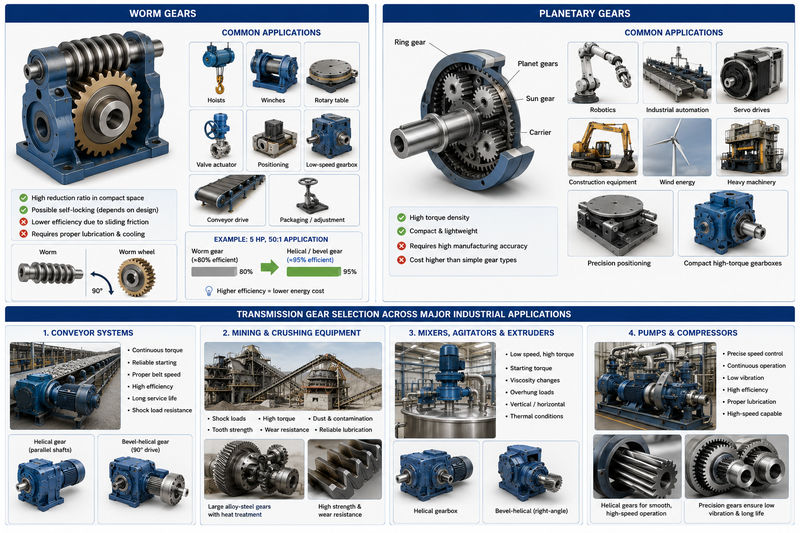
A worm gear consists of a worm shaft, which resembles a threaded screw, and a mating worm wheel.
Worm gear systems are useful because they can provide substantial speed reduction within a compact arrangement and typically operate with shafts at approximately 90 degrees.
Common industrial applications include:
- Hoisting equipment
- Winches
- Rotary tables
- Valve actuators
- Positioning mechanisms
- Low-speed gearboxes
- Certain conveyor drives
- Packaging and adjustment equipment
One important characteristic is the possibility of self-locking in suitable designs. Under specific geometry and friction conditions, the output side may resist back-driving the worm. This can be useful in lifting and positioning applications, although self-locking should never be assumed without evaluating the actual gear geometry, lubrication, load, vibration, and service conditions.
The primary engineering challenge is sliding friction.
Unlike many conventional gear pairs that mainly experience rolling contact, worm gear systems have significant sliding contact. This increases heat generation and makes lubrication especially important.
As a result, a worm gearbox should not be selected simply because it can provide a large reduction ratio. For a continuously operating industrial drive, engineers should compare efficiency, thermal capacity, service hours, and electricity consumption against alternative helical or bevel-helical solutions.
A U.S. Department of Energy industrial guide gives an example of replacing an 80% efficient worm gear with a 95% efficient helical/bevel gear arrangement in a 5 hp, 50:1 application, illustrating why gearbox efficiency can become a significant operating-cost issue in long-running equipment. Industrial Uses of Transmission Gears
Planetary Gears for High Torque in Compact Systems
Planetary gear systems generally include a sun gear, multiple planet gears, a planet carrier, and an internal ring gear.
Their major advantage is torque density. Multiple planet gears can share the transmitted load, allowing a compact gearbox to transmit substantial torque.
Planetary transmission systems are widely used in:
- Robotics
- Industrial automation
- Servo drives
- Construction equipment
- Wind energy systems
- Heavy-duty machinery
- Precision positioning equipment
- Compact high-torque gearboxes
For example, an industrial robot joint has limited installation space but may require a high reduction ratio and substantial output torque. A planetary gearbox can provide a compact solution compared with a large conventional multi-stage parallel-shaft gearbox.
Manufacturing accuracy is particularly important because the planets must distribute load correctly. Errors in tooth geometry, carrier position, shaft alignment, or internal gear concentricity can cause unequal load sharing.
Transmission Gear Selection Across Major Industrial Applications
The correct gear type depends on the actual work performed by the machine. A gearbox specification should begin with the application rather than with the question, “Which gear is strongest?”
A stronger gear is not automatically a better gear. If it creates excessive friction, consumes unnecessary power, does not fit the shaft arrangement, or is too expensive to manufacture, it may be the wrong solution.
Conveyor Systems
Conveyors are one of the most common industrial uses of transmission gears.
The gearbox must typically provide:
- Continuous torque
- Reliable starting under load
- Appropriate belt speed
- High efficiency
- Long service life
- Resistance to shock loads
Helical gears are commonly suitable for parallel-shaft conveyor drives because of their smooth operation and efficiency.
For conveyors where the output shaft must operate at 90 degrees to the motor, bevel-helical gearboxes may provide an efficient right-angle solution.
The selection should account for starting torque rather than only normal running torque. A conveyor carrying bulk material may experience significantly higher torque during startup, particularly when material is already resting on the belt.
Mining and Crushing Equipment
Mining equipment places extremely demanding requirements on transmission gears.
Examples include:
- Crushers
- Conveyors
- Excavating machinery
- Grinding mills
- Feeders
- Screening equipment
These systems can experience shock loading, dust contamination, high torque, and long operating hours.
The gear design must therefore address tooth bending strength, contact fatigue, surface wear, lubrication, and contamination control.
Large alloy-steel gears with appropriate heat treatment are common in these applications. Material selection may also depend on gear size because a large gear requires sufficient hardenability through its section.
A gear that is dimensionally correct but has inadequate core strength can crack under repeated impact. Conversely, a gear with an extremely hard surface but poor toughness may become vulnerable to cracking or tooth-root failure. Industrial Uses of Transmission Gears
Mixers, Agitators, and Extruders
Industrial mixers and agitators often require low speed and high torque.
The resistance produced by the material being mixed can also change during operation. A mixer handling a low-viscosity liquid behaves very differently from one processing high-viscosity compounds, slurries, polymers, or dense industrial materials.
Gear selection must therefore consider:
- Continuous torque
- Starting torque
- Viscosity changes
- Overhung loads
- Vertical or horizontal shaft layout
- Thermal operating conditions
Helical and bevel-helical transmissions are widely applicable because they can provide efficient continuous operation.
For vertical mixers, right-angle arrangements are particularly useful because they allow the motor and output shaft to be arranged efficiently within the available machine structure.
Pumps and Compressors
Pump and compressor transmission systems may require precise speed control and continuous operation.
The gear system must minimize unnecessary vibration because vibration can affect bearings, seals, couplings, and connected process equipment.
Helical gears are frequently suitable for higher-speed applications because of their smoother engagement. Gear accuracy, shaft runout, backlash, and tooth surface quality can become increasingly important as speed increases.
In high-speed equipment, lubrication must also be designed correctly. Oil that is sufficient for a slow gearbox may not provide the same performance when centrifugal forces, churning losses, and heat generation become significant.
Machine Tools and Automated Manufacturing
Transmission gears are used throughout industrial machine tools and automated equipment.
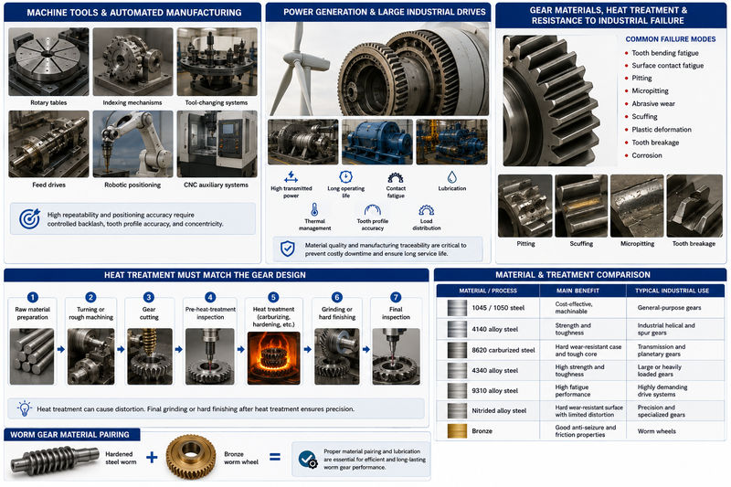
Applications include:
- Rotary tables
- Indexing mechanisms
- Tool-changing systems
- Feed drives
- Robotic positioning
- CNC auxiliary systems
These applications often prioritize repeatability and positioning accuracy in addition to torque transmission.
A gear may need carefully controlled backlash, tooth profile accuracy, and concentricity. In some systems, the manufacturing tolerance of the gear directly affects the positioning performance of the complete machine.
Power Generation and Large Industrial Drives
Transmission gears are also used in wind turbines, turbine systems, generators, and other large-scale power equipment.
These applications require attention to:
- High transmitted power
- Long operating life
- Contact fatigue
- Lubrication
- Thermal management
- Tooth profile accuracy
- Load distribution
Large industrial gears are expensive components, and replacement may require substantial machine downtime. For this reason, material quality and manufacturing traceability can be as important as the initial dimensional inspection.
Gear Materials, Heat Treatment, and Resistance to Industrial Failure
Material selection has a direct influence on gear life.
An industrial gear must resist several different failure mechanisms, including:
- Tooth bending fatigue
- Surface contact fatigue
- Pitting
- Micropitting
- Abrasive wear
- Scuffing
- Plastic deformation
- Tooth breakage
- Corrosion
Different materials and heat-treatment processes are selected to address different combinations of these risks.
Carbon Steel for General-Purpose Gears
Medium-carbon steels such as 1045 or 1050 can be used for certain general industrial applications.
Their advantages include:
- Good machinability
- Relatively low cost
- Simple availability
- Suitability for moderate-duty components
These materials may be appropriate where the load and speed are moderate and extreme surface hardness is not required.
However, they may not provide the same fatigue and wear performance as properly carburized alloy steels in heavily loaded, high-cycle transmission systems.
4140 Alloy Steel for Strong General Industrial Gears
4140 is widely used in industrial power transmission because it offers a useful combination of strength, toughness, and hardenability.
It can be used with different heat-treatment routes depending on the application.
Typical applications include:
- Industrial helical gears
- Heavy-duty spur gears
- Gear shafts
- General gearbox components
For medium- to high-load applications, 4140 may provide a practical balance between manufacturing cost and mechanical performance.
8620 Case-Hardening Steel for High-Wear Transmission Gears
8620 is a well-known carburizing steel for gears requiring a hard surface and a tough core.
After carburizing and appropriate quenching and tempering, the outer tooth surface can achieve high hardness while the interior remains comparatively tough.
This combination is valuable because gear teeth require two different properties.
The tooth surface must resist wear and repeated contact stress. At the same time, the gear body and tooth root must resist bending and shock without becoming excessively brittle.
This makes carburized alloy steel particularly suitable for:
- Transmission gears
- Planetary gears
- Industrial reducers
- Automotive and heavy-duty drive components
- High-cycle power transmission systems
Published gear material references commonly identify 4140 as a versatile industrial gear steel and 8620 as a common case-hardening choice where high surface wear resistance and a tougher core are required. Higher-demand applications may use materials such as 4340 or 9310 depending on loading and performance requirements.
Heat Treatment Must Match the Gear Design
Heat treatment should not be treated as a separate final operation.
The complete manufacturing sequence must be planned from the beginning.
A typical precision steel gear manufacturing route may include:
- Raw material preparation
- Turning or rough machining
- Gear cutting
- Pre-heat-treatment inspection
- Carburizing, hardening, nitriding, or through-hardening
- Grinding or hard finishing
- Final inspection
Heat treatment can cause dimensional distortion. If a gear is machined completely to final dimensions before carburizing and quenching, the distortion may push the tooth geometry outside the required tolerance.
For this reason, high-precision gears are often finished by gear grinding or other hard-finishing processes after heat treatment.
The exact process depends on gear size, module, material, quality requirements, production volume, and cost target.
Material and Treatment Comparison
| Material / Process | Main Benefit | Typical Industrial Use |
|---|---|---|
| 1045 / 1050 steel | Cost-effective, machinable | General-purpose gears |
| 4140 alloy steel | Strength and toughness | Industrial helical and spur gears |
| 8620 carburized steel | Hard wear-resistant case and tough core | Transmission and planetary gears |
| 4340 alloy steel | High strength and toughness | Large or heavily loaded gears |
| 9310 alloy steel | High fatigue performance | Highly demanding drive systems |
| Nitrided alloy steel | Hard wear-resistant surface with limited distortion | Precision and specialized gears |
| Bronze | Good anti-seizure and friction properties | Worm wheels |
For worm gear pairs, material pairing is particularly important. A hardened steel worm is often matched with a bronze wheel because the combination helps manage sliding contact and reduces the risk of seizure.
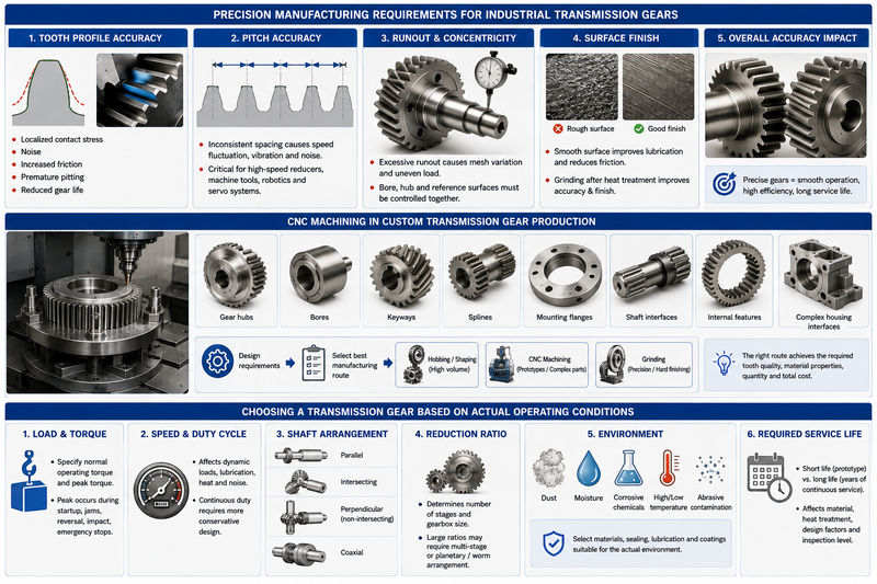
Precision Manufacturing Requirements for Industrial Transmission Gears
Industrial gear performance depends heavily on manufacturing accuracy.
A gear can have the correct number of teeth and outside diameter but still perform poorly if the tooth profile, lead, pitch, runout, or surface finish is outside the required tolerance.
Tooth Profile Accuracy
The tooth profile determines how contact is distributed during meshing.
An incorrect profile can cause:
- Localized contact stress
- Noise
- Increased friction
- Uneven load distribution
- Premature pitting
- Reduced transmission life
For a heavily loaded gear, small deviations can create a concentrated contact area instead of distributing the load across the intended tooth surface.
This increases local stress and accelerates fatigue.
Pitch Accuracy and Transmission Smoothness
Pitch error affects the spacing between teeth.
If tooth spacing is inconsistent, the angular velocity transmitted through the gear pair can fluctuate. At higher speeds, these fluctuations can increase vibration and noise.
This is particularly important in:
- High-speed reducers
- Machine tools
- Precision automation
- Robotics
- Servo transmission systems
Runout and Concentricity
Runout occurs when the gear does not rotate perfectly around its intended axis.
Excessive runout can cause periodic changes in mesh quality and load distribution.
For a CNC-machined gear, the relationship between the bore, hub, reference surfaces, and tooth geometry must therefore be controlled carefully.
A gear manufacturer should not inspect tooth geometry in isolation. The final component must also be evaluated relative to the mounting features used in the actual transmission assembly.
Surface Finish and Gear Life
Surface finish affects lubrication behavior and friction.
A rough tooth surface can damage the lubricating film and create localized high points. Under repeated load, these areas may contribute to micropitting or accelerated wear.
For hardened precision gears, grinding after heat treatment can improve final tooth geometry and surface finish while correcting distortion introduced during hardening.
However, excessive grinding can also create thermal damage if the process is poorly controlled. Manufacturing quality therefore depends not only on selecting the right process but also on controlling process parameters.
CNC Machining in Custom Transmission Gear Production
CNC machining is especially valuable for custom gears, prototypes, low-volume production, replacement parts, and complex transmission components.
A CNC manufacturing process can be used for related gear features such as:
- Gear hubs
- Bores
- Keyways
- Splines
- Mounting flanges
- Shaft interfaces
- Internal features
- Complex housing interfaces
For certain custom projects, multi-axis CNC machining is particularly useful when the gear component includes complex geometry that cannot be produced efficiently using conventional methods alone.
However, the manufacturing method should be selected according to the gear design.
High-volume standard spur and helical gears may be efficiently produced using specialized hobbing or shaping processes. Complex prototypes or integrated components may benefit from CNC machining. Precision hard finishing may require gear grinding.
The correct question is therefore not, “Can this gear be CNC machined?”
The more useful engineering question is:
Which manufacturing route can achieve the required tooth quality, material properties, production quantity, and total cost?
Choosing a Transmission Gear Based on Actual Operating Conditions
Before manufacturing or sourcing an industrial transmission gear, the following information should be clearly defined.
Load and Torque
Specify both normal operating torque and peak torque.
Peak torque may occur during:
- Startup
- Emergency stops
- Material jams
- Direction reversal
- Impact loading
A gear designed only for average torque may fail under repeated overload events.
Speed and Duty Cycle
Operating speed affects dynamic loading, lubrication requirements, heat generation, and noise.
A gear operating for five minutes per hour does not experience the same thermal and fatigue conditions as one operating continuously.
Shaft Arrangement
Determine whether shafts are:
- Parallel
- Intersecting
- Perpendicular and non-intersecting
- Coaxial
This immediately narrows the suitable gear designs.
Reduction Ratio
The required ratio affects the number of gear stages and gearbox size.
Very large ratios may require multiple stages or a specialized arrangement such as planetary or worm transmission.
Environment
Industrial environments may introduce:
- Dust
- Moisture
- Corrosive chemicals
- High temperature
- Low temperature
- Abrasive contamination
A gear that performs well in a clean factory environment may fail rapidly in mining or chemical processing if sealing and lubrication are inadequate.
Required Service Life
The expected service life influences material selection, tooth design, heat treatment, and inspection requirements.
A prototype machine may need only limited operating life. A production gearbox operating continuously for years requires a much more conservative approach.
Xavier: Precision Manufacturing Support for Custom Industrial Transmission Gears
Industrial transmission gears are not generic components when they are used in demanding machinery. The correct solution depends on the interaction between gear geometry, material, heat treatment, machining accuracy, load conditions, lubrication, and the overall transmission layout.
For custom industrial equipment, replacement gearbox components, prototypes, and precision power transmission parts, Xavier can support the manufacturing of complex gear-related components and precision machined parts based on customer drawings and technical requirements.
From selecting machinable materials such as carbon steel, 4140 alloy steel, 8620-type gear steels, stainless steel, aluminum alloys, and engineering plastics for appropriate applications, to machining bores, hubs, shafts, splines, keyways, mounting features, and complex transmission interfaces, Xavier focuses on producing components that match the functional requirements of the complete assembly.
For projects involving industrial transmission gears, the most useful starting point is a complete drawing together with the key operating information: transmitted torque, speed, gear ratio, material requirement, heat treatment, hardness, accuracy requirement, and intended application.
With those details clearly defined, Xavier can help turn a custom transmission component from an engineering drawing into a practical precision-manufactured part for industrial machinery.
We are an integrated CNC manufacturing supplier specializing in CNC machining services, with a strong focus on custom machining and the production of precision metal parts. We also support a range of professional surface finishing options, including CNC anodizing surface finishing, CNC electrogalvanizing surface finishing, and CNC chemical conversion coating.
For your manufacturing needs, we are a CNC anodizing manufacturer offering CNC electrogalvanizing services in bulk. If you need a quotation, feel free to contact us for CNC chemical conversion coating pricing.
Some of the images and text in this article are collected and compiled from the internet. If there is anything inappropriate, please contact us for processing.