
Drone Frame CNC Milling: Materials, Structural Design, Precision Tolerances, and Manufacturing Methods
A drone frame is more than a lightweight structure that holds motors, batteries, and electronic components together. It is the mechanical foundation that determines how thrust loads are transferred, how vibration reaches onboard sensors, how accurately components align, and how reliably the aircraft performs after repeated takeoffs, landings, and changes in payload.
From a manufacturing and procurement perspective, drone frame CNC milling is particularly valuable when a UAV requires accurate mounting interfaces, complex lightweight geometries, consistent assembly dimensions, and repeatable production quality. However, the best frame is not necessarily the one with the tightest tolerances or the greatest amount of material removed. It is the one that meets the actual structural, weight, cost, and service-life requirements without introducing unnecessary manufacturing difficulty.
Recent industry articles on drone frame machining and UAV component manufacturing repeatedly emphasize five practical subjects: material selection, lightweight structural design, machining accuracy, manufacturing processes, and quality verification.
Five Key Topics Covered in This Article
- Drone Frame Materials: Choosing between 6061-T6 aluminum, 7075-T6 aluminum, titanium, and carbon fiber composites.
- Lightweight Frame Design: Optimizing pockets, ribs, wall thicknesses, mounting points, and structural stiffness.
- CNC Milling Accuracy and Tolerances: Controlling flatness, hole positions, motor alignment, and thin-wall deformation.
- CNC Milling Processes and Manufacturing Costs: Selecting machining strategies, tooling, workholding, and production routes.
- Surface Finishing, Inspection, and Supplier Selection: Managing corrosion protection, dimensional verification, and repeatable manufacturing quality.
1. Drone Frame Materials: Choosing Between 6061-T6, 7075-T6, Titanium, and Carbon Fiber
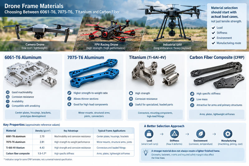
The material selected for a drone frame affects its structural stiffness, fatigue resistance, machining cost, weight, corrosion behavior, and assembly reliability. From a procurement standpoint, material selection should begin with the frame’s actual load cases rather than a simple comparison of tensile strength.
A lightweight camera drone, an FPV racing drone, and a long-endurance industrial UAV do not necessarily need the same material. A frame supporting a small camera may prioritize low cost and efficient machining, while a heavy-payload UAV may need stronger motor mounts and reinforced arm connections to withstand repeated vibration and landing loads.
6061-T6 Aluminum: Practical for General-Purpose Drone Frames
6061-T6 aluminum is widely used for structural brackets, electronics housings, center plates, battery mounts, and general-purpose UAV components. Its principal advantages are good machinability, corrosion resistance, availability, and compatibility with anodizing.
For example, a 6061-T6 center plate with machined pockets and mounting holes can provide a rigid platform for a flight controller, battery, and payload electronics. The material is also useful during prototype development, when the design may undergo several revisions before production.
The limitation is that 6061-T6 generally has lower strength than 7075-T6. If a motor arm is subjected to substantial cyclic bending, simply reducing its thickness to save weight can compromise stiffness and fatigue life.
7075-T6 Aluminum: For High-Load Structural Components
7075-T6 is often considered for motor mounts, high-load arm joints, structural connectors, and compact UAV components where strength-to-weight performance is important. Its higher strength can allow engineers to reduce material in selected regions while maintaining the required load capacity.
However, the alloy is not automatically the best choice for every frame. It typically costs more than 6061-T6, is less forgiving in some manufacturing and joining operations, and needs an appropriate corrosion-protection strategy.
Titanium and Carbon Fiber: Different Solutions to Different Problems
Titanium alloys such as Ti-6Al-4V are useful for highly loaded connectors, specialized mounting components, and parts requiring a combination of strength and corrosion resistance. Their disadvantages include higher material cost, greater cutting difficulty, and longer machining cycles.
Carbon fiber reinforced polymer (CFRP) is different because it is a composite rather than a homogeneous metal. It offers high specific stiffness and low mass, making it attractive for arms, plates, and primary structures. However, machining can cause fiber pull-out, delamination, edge damage, and hazardous airborne dust if the process is poorly controlled.
The following properties are approximate reference values for material screening. Actual values depend on alloy specification, product form, heat treatment, fiber orientation, and supplier certification.
| Material | Approx. density (g/cm³) | Key advantage | Typical frame applications |
|---|---|---|---|
| 6061-T6 aluminum | 2.70 | Machinability and corrosion resistance | Center plates, housings, brackets |
| 7075-T6 aluminum | 2.81 | High strength-to-weight performance | Motor mounts, structural arms, joints |
| Ti-6Al-4V titanium | 4.43 | High strength and corrosion resistance | Specialized connectors and loaded fittings |
| Carbon fiber composite | 1.5–1.7* | High specific stiffness | Arms, plates, lightweight airframes |
*Indicative range for some CFRP laminates, not a universal material specification.
A useful preliminary selection rule is to evaluate the load, stiffness, environment, and manufacturing route together. A stronger material does not always create a lighter finished frame because the geometry, fasteners, inserts, and required safety margins also affect total mass.
2. Lightweight Drone Frame Design: Pocket Milling, Ribs, Wall Thickness, and Structural Stiffness
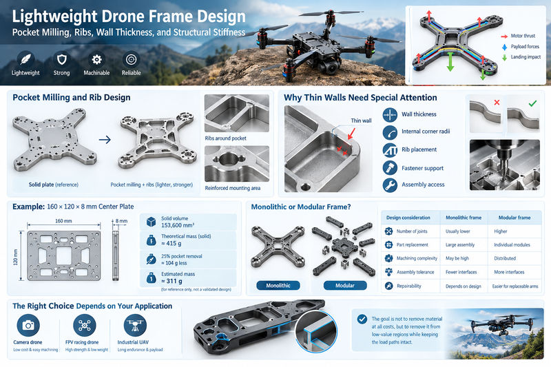
The objective of lightweight frame design is not to remove as much material as possible. It is to remove material from low-value regions while preserving the load paths that transfer motor thrust, payload forces, and landing impacts through the structure.
Pocket Milling and Rib Design
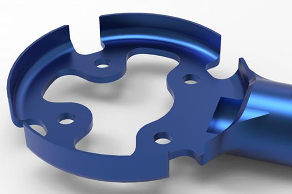
Pocket milling creates recessed regions in a solid aluminum component, reducing mass without removing all the material between mounting points. Ribs provide localized reinforcement around these pockets, bolt holes, and other high-load areas.
Consider a hypothetical aluminum center plate measuring 160 × 120 × 8 mm. Its gross rectangular volume is:
[ V=160\times120\times8=153{,}600\ \text{mm}^3 ]
At a density of 2.70 g/cm³, the theoretical mass of the solid plate is approximately 415 g before accounting for holes, chamfers, and other features.
If a pocketing strategy removes 25% of the original volume, the theoretical mass reduction is approximately 104 g, leaving about 311 g. These figures illustrate the arithmetic, not a validated structural design. Whether the lighter plate can withstand operational loads must be established through engineering analysis and testing.
Why Thin Walls Need Special Attention
Thin walls are more susceptible to cutting forces, chatter, thermal effects, and elastic deformation. A wall may measure correctly while clamped but spring out of shape after the fixture is released.
A practical design review should examine the following:
- Wall thickness: Avoid unnecessarily thin walls, particularly around deep pockets and long unsupported sections.
- Internal corner radii: Use radii compatible with available cutting tools. Very small internal corners require smaller, less rigid end mills and additional machining time.
- Rib placement: Add material near load paths, mounting bosses, and arm connections rather than uniformly thickening the whole frame.
- Fastener support: Provide enough material around threaded holes and counterbores to resist local bearing and clamping loads.
- Assembly access: Ensure tools can reach fasteners and that adjacent components can be installed without interference.
Monolithic or Modular Frame Construction?
A monolithic frame can reduce the number of joints and simplify datum relationships. However, a single complex component may require extensive material removal, longer machining time, and more expensive fixtures.
A modular frame uses separate arms, center plates, motor mounts, and connecting brackets. This arrangement can simplify replacement and allow individual components to be revised without remanufacturing the entire frame. The trade-off is that each joint introduces additional interfaces, fasteners, and potential alignment errors.
| Design consideration | Monolithic frame | Modular frame |
|---|---|---|
| Number of joints | Usually lower | Higher |
| Part replacement | May require replacing a large assembly | Individual modules can be replaced |
| Machining complexity | May be high for complex geometries | Distributed across separate components |
| Assembly tolerance stack-up | Fewer interfaces | More interfaces to control |
| Repairability | Depends on component architecture | Often easier for replaceable arms |
For a drone intended for field service, a modular design may be more practical even if the one-piece design looks cleaner in CAD. The final decision should reflect expected damage, repair procedures, structural loads, and production volume.
3. CNC Milling Accuracy and Tolerances: Motor Alignment, Hole Position, and Flatness
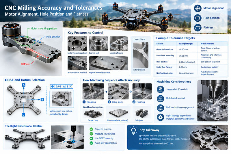
Precision is not simply a matter of producing a dimension close to its nominal value. For a drone frame, the relationship between mounting faces, bolt patterns, motor axes, and adjoining components often matters more than the overall dimensions of the part.
A frame can pass a basic length-and-width inspection and still cause assembly problems if its motor mounting faces are not properly oriented or its arm attachment holes do not align.
Which Dimensions Need Tight Control?
Typical critical features include motor mounting patterns, bearing seats, locating features, arm-to-center-plate interfaces, and payload mounting surfaces. Less critical features, such as nonfunctional exterior reliefs, usually do not need the same tolerance level.
The values below are illustrative starting points for a machining discussion, not universal drone or aerospace requirements.
| Feature | Example preliminary target | Why it matters |
|---|---|---|
| General machined dimensions | ±0.10 mm | Basic fit and envelope control |
| Functional mounting dimensions | ±0.05 mm | Assembly and interface consistency |
| Critical hole position | Position tolerance of 0.05 mm | Bolt-pattern alignment |
| Motor mounting face flatness | 0.05 mm | Contact and mounting stability |
| Nonfunctional cosmetic edges | General drawing tolerance | Avoids unnecessary inspection cost |
These example values must be reviewed against the actual design, manufacturing capability, measurement uncertainty, and assembly tolerance stack-up. A position tolerance of 0.05 mm is a geometric control and should not be treated as interchangeable with a simple ±0.05 mm coordinate tolerance.
GD&T and Datum Selection
Geometric dimensioning and tolerancing (GD&T) communicates the relationship between features through defined datums and geometric controls. ASME Y14.5 provides an established framework for specifying and interpreting these requirements.
For a modular quadcopter frame, a sensible datum strategy might use:
- Datum A: the principal mounting surface of the center plate.
- Datum B: a machined side or locating feature.
- Datum C: a secondary locating hole or feature that establishes the remaining orientation.
The motor-mount hole pattern can then be controlled relative to the intended datum reference frame. This is more meaningful than measuring each hole independently without considering how the motor mount actually locates during assembly.
How Machining Sequence Affects Accuracy
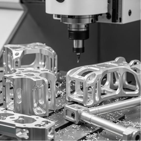
A common manufacturing approach is to rough-machine the major pockets, leave sufficient stock for finishing, and then finish the critical surfaces after the part has stabilized. Depending on the alloy, geometry, and starting material, stress-relief measures or a different machining sequence may be necessary.
For a thin center plate, the machinist may use distributed support, soft jaws, vacuum workholding where suitable, and reduced cutting engagement during finishing. The correct strategy depends on the part’s rigidity and the fixture design.
The key purchasing lesson is to specify the features that affect function and ask the supplier how those features will be measured. Requesting ±0.01 mm on every dimension without a functional reason can raise machining and inspection costs substantially without necessarily improving flight performance.
4. CNC Milling Processes and Manufacturing Costs: From CAD to Finished Frame
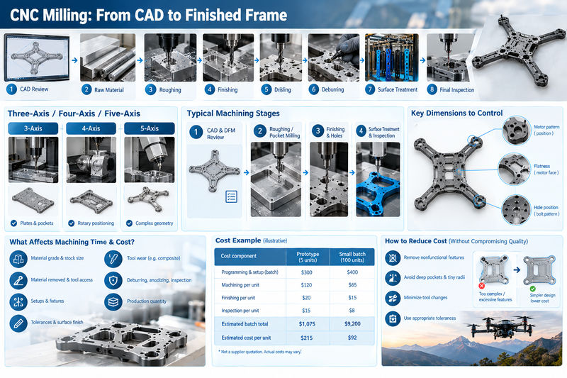
The manufacturing route for a drone frame typically involves CAD review, raw-material preparation, roughing, finishing, drilling, deburring, surface treatment where required, and final inspection. The order and equipment depend on whether the component is a flat plate, a complex three-dimensional structure, or a thin-walled integrated assembly.
Three-Axis, Four-Axis, and Five-Axis Machining
Three-axis CNC milling is well suited to plates, pockets, slots, and features accessible from the top and sides with planned setups. Four-axis machining adds rotary positioning, which can reduce manual repositioning for selected geometries. Five-axis machining can access more complex orientations and may reduce setup changes for parts with angled surfaces or features distributed across multiple faces.
Five-axis machining is not automatically more economical. If the frame consists mainly of flat plates and simple pockets, three-axis machining may deliver the required accuracy at a lower cost. The appropriate machine should be selected according to geometry, datum continuity, access, and production quantity.
Typical Manufacturing Stages
Stage 1 — CAD and DFM review
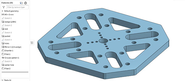
Check material, wall thickness, internal radii, hole patterns, tool access, datum scheme, and weight targets before releasing the drawing.
Stage 2 — Roughing and pocket milling
Remove bulk material using suitable cutting tools and workholding while preserving sufficient stock for final dimensions.
Stage 3 — Finishing and hole machining
Finish critical surfaces, drill or interpolate mounting holes, and control burrs around interfaces and fastener openings.
Stage 4 — Finishing and inspection
Apply the specified surface treatment, inspect critical features, verify assembly fit, and document results against the drawing.
What Determines Machining Time and Unit Cost?
Machining cost depends on more than the size of the finished frame. A small part with deep pockets, narrow slots, many threaded holes, and difficult-to-reach surfaces can take longer to produce than a larger but simpler plate.
The main cost drivers include:
- Raw-material grade and stock dimensions.
- Material removed and cutting-tool accessibility.
- Number of setups and fixture complexity.
- Required tolerances and surface finish.
- Tool wear, especially when machining abrasive composite materials.
- Deburring, anodizing, inspection, and documentation.
- Production quantity and repeatability requirements.
The following is a hypothetical planning example to show how the cost structure changes. It is not a supplier quotation.
| Cost component | Prototype, 5 units | Small batch, 100 units |
|---|---|---|
| Programming and setup per batch | $300 | $400 |
| Machining per unit | $120 | $65 |
| Finishing per unit | $20 | $15 |
| Inspection per unit | $15 | $8 |
| Estimated batch total | $1,075 | $9,200 |
| Estimated cost per unit | $215 | $92 |
In this example, setup costs are distributed across more units in the larger batch, while the assumed machining and inspection costs per unit are lower. Actual results may differ considerably with part geometry, supplier rates, tooling, and inspection requirements.
How to Reduce Cost Without Compromising the Frame
Start by simplifying nonfunctional features. Avoid unnecessarily deep pockets, tiny internal radii, excessive tool changes, and blanket tight tolerances. If a mounting interface needs precise control, keep that requirement; if an external relief has no functional purpose, use an appropriate general tolerance.
For repeated orders, ask whether a dedicated fixture, standardized toolpath, or combined inspection plan can improve consistency. For early prototypes, however, it is often better to validate the structural design before investing in production-specific tooling.
5. Surface Finishing, Quality Inspection, and CNC Supplier Selection
A drone frame must survive its operating environment as well as fit correctly during assembly. Surface finishing can improve corrosion protection, wear resistance, and appearance, but a coating can also change critical dimensions.
Anodizing and Other Surface Treatments
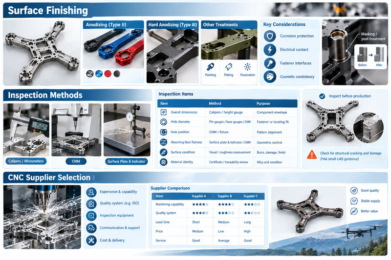
Anodizing is commonly used on aluminum frame components. Type II anodizing can provide a protective oxide layer and optional coloring, while Type III hard anodizing is considered when greater surface hardness and wear resistance are required.
The correct treatment depends on alloy, operating environment, contact surfaces, and dimensional requirements. For example, a close-fitting bore or locating interface may require masking, post-treatment machining, or explicit allowance for coating growth. A drawing should identify whether the specified dimension applies before or after finishing.
Other considerations include:
- Corrosion protection: Important for outdoor inspection drones, marine environments, and equipment exposed to moisture.
- Electrical contact: Anodized surfaces are generally electrically insulating, so grounding or bonding locations may need special treatment.
- Fastener interfaces: Coating thickness and friction can influence fit, clamping behavior, and assembly.
- Cosmetic consistency: Color variation can occur between alloys, batches, and process conditions.
Inspection Methods That Matter
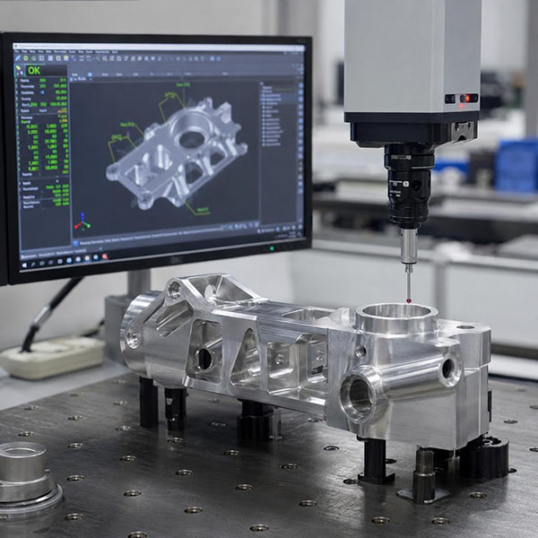
Inspection should focus on both dimensional compliance and the features that affect assembly. Calipers and micrometers are suitable for many accessible dimensions, while a coordinate measuring machine (CMM) can verify complex hole patterns, datum relationships, and geometric tolerances when the measurement strategy is appropriate. drone frame CNC milling
A robust inspection plan may include:
| Inspection item | Suitable method | Purpose |
|---|---|---|
| Overall dimensions | Calipers or height gauge | Confirm the component envelope |
| Hole diameter | Pin gauges, bore gauges, or CMM | Verify fastener or locating fit |
| Hole position | CMM or appropriate positional fixture | Check pattern alignment |
| Mounting-face flatness | Surface plate and indicator, or CMM | Verify the required geometric control |
| Surface condition | Visual inspection and specified roughness measurement | Identify burrs, damage, or finish defects |
| Material identity | Material certificate and traceability review | Confirm the specified alloy and condition |
Inspection criteria should be established before production rather than after parts have been manufactured. The FAA’s small-UAS guidance also identifies structural cracking and damage as conditions requiring further inspection before continued operation.
What to Ask Before Selecting a CNC Supplier
For procurement teams, a competitive unit price is only one part of supplier qualification. The supplier should understand the component’s functional requirements and explain how those requirements will be achieved and verified.
Before placing an order, confirm the following:
- Material traceability: Can the supplier identify the alloy and temper and provide the documentation required for the project?
- Machining capability: Does the supplier have the equipment, workholding, and tooling needed for the geometry?
- Tolerance review: Will the supplier identify dimensions that are difficult or unnecessarily expensive to hold?
- Inspection capability: Can the supplier verify the specified geometric tolerances and provide an inspection report when required?
- Surface treatment: Is the coating process compatible with the selected material and finished dimensions?
- Production repeatability: Can the supplier maintain the same process and acceptance criteria across repeat orders?
- Change management: Will drawing revisions, material substitutions, or process changes be reviewed and approved before implementation?
For flight-critical or regulated aerospace applications, the required quality-management approvals, material specifications, process qualifications, and documentation must be evaluated against the actual contract and applicable standards. A general CNC machining capability alone does not establish aerospace qualification.
Conclusion: Custom Drone Frame CNC Milling by Xavier
A successful drone frame is the result of coordinated decisions about material, structural geometry, machining strategy, tolerances, surface treatment, and inspection. Choosing 7075-T6 instead of 6061-T6 may improve strength in a highly loaded component, but it will not compensate for poor rib placement, weak fastener interfaces, or an unsuitable machining sequence. Likewise, a very tight hole tolerance cannot correct a mounting face that is not properly controlled relative to its functional datums.
For buyers developing a new UAV or improving an existing design, the most productive approach is to review the complete component drawing before requesting production pricing. Identify the critical interfaces, state the material and finish requirements, define the required inspection records, and make the target quantity and delivery schedule clear.
Xavier provides CNC machining services for custom metal components and can support manufacturing discussions involving drone frames, structural plates, motor mounts, brackets, and other precision-machined parts. By reviewing your CAD files, material requirements, critical tolerances, and surface-finish specifications, the Xavier team can help assess a suitable manufacturing route for your project.
If you are sourcing custom drone frame CNC milling, send Xavier your 2D drawings or 3D CAD files, target quantity, material specification, and required finish for a project-specific quotation and manufacturability review.
As an integrated CNC machining manufacturer and trading company, we specialize in CNC contract manufacturing and the precision machining of various metal components. Our capabilities also cover CNC milling for aluminum parts, CNC turning for stainless steel components, and 5-axis CNC machining for titanium parts. We work with a broad range of metals and engineering plastics, including alloy steel, aluminum, brass, bronze, copper, Inconel, Invar 36, mild steel, stainless steel, titanium, tool steel, ABS, FR4, G-10, nylon, PEEK, PEI, PET, PMMA (acrylic), polycarbonate, polyethylene, polypropylene, POM (acetal), PPSU, PTFE, and PVC. Our precision machining solutions serve diverse industries, supplying custom components for robotics, aerospace, marine equipment, automotive systems, medical devices, and other demanding industrial applications.
As a reliable aluminum CNC machining manufacturer, we provide high-volume stainless steel CNC turning services for customers seeking consistent quality and dependable production. Contact us to discuss your project requirements and obtain competitive titanium CNC machining prices. We look forward to supporting your custom manufacturing needs.
Some of the images and text in this article are collected and compiled from the internet. If there is anything inappropriate, please contact us for processing.