
Custom UAV Parts Manufacturing: CNC Machining Guide for Drone Components
When I review a custom UAV component as a procurement engineer, I do not start by asking, “What is the machining price?”
I start with a different question:
What does this part have to do during flight, and what happens if it is 0.05 mm out of position?
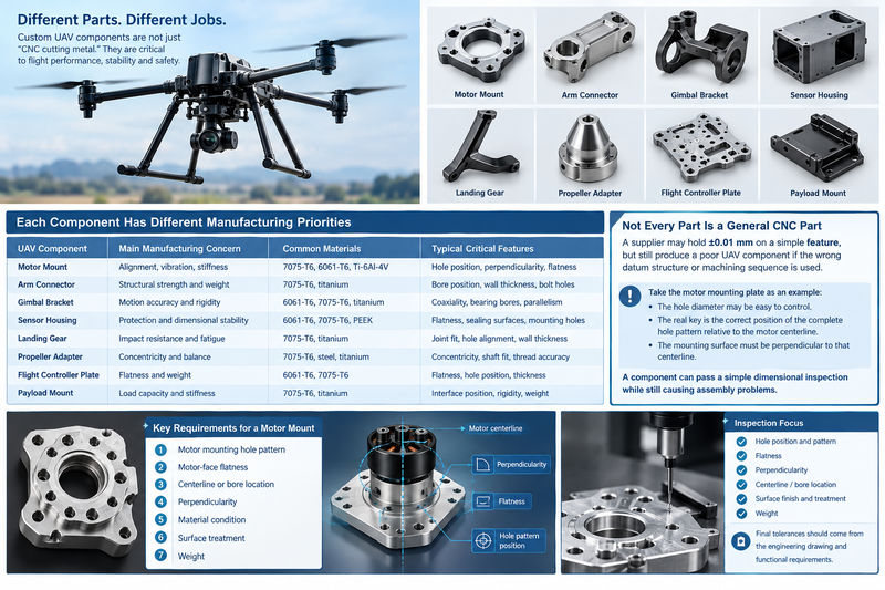
A drone motor mount, gimbal bracket, landing gear connector, battery tray, sensor housing, propeller adapter, or flight-control plate may look relatively simple on a drawing. In reality, each component has a different mechanical job. A motor mount must control alignment and vibration. A gimbal component must maintain rotational accuracy. A structural arm connector must carry repeated loads without unnecessary weight. A sensor housing may need dimensional stability rather than extreme mechanical strength.
That is why custom UAV parts manufacturing should be treated as an engineering process rather than simply “CNC cutting metal.”
The five areas below are the ones I would examine first when qualifying a CNC supplier for UAV components.
The first mistake I see in sourcing is treating every UAV component as a general CNC part.
It is not.
A drone can contain dozens or even hundreds of machined components, but their manufacturing priorities are completely different.
| UAV Component | Main Manufacturing Concern | Common Materials | Typical Critical Features |
|---|---|---|---|
| Motor Mount | Alignment, vibration, stiffness | 7075-T6, 6061-T6, Ti-6Al-4V | Hole position, perpendicularity, flatness |
| Arm Connector | Structural strength and weight | 7075-T6, titanium | Bore position, wall thickness, bolt holes |
| Gimbal Bracket | Motion accuracy and rigidity | 6061-T6, 7075-T6, titanium | Coaxiality, bearing bores, parallelism |
| Sensor Housing | Protection and dimensional stability | 6061-T6, 7075-T6, PEEK | Flatness, sealing surfaces, mounting holes |
| Landing Gear | Impact resistance and fatigue | 7075-T6, titanium | Joint fit, hole alignment, wall thickness |
| Propeller Adapter | Concentricity and balance | 7075-T6, steel, titanium | Concentricity, shaft fit, thread accuracy |
| Flight Controller Plate | Flatness and weight | 6061-T6, 7075-T6 | Flatness, hole position, thickness |
| Payload Mount | Load capacity and stiffness | 7075-T6, titanium | Interface position, rigidity, weight |
This distinction is important because a supplier may be able to hold ±0.01 mm on a simple feature but still produce a poor UAV component if the wrong datum structure or machining sequence is used.
For example, suppose a motor mounting plate has eight bolt holes.
The hole diameter might be relatively easy to control. The more important question may be whether the complete hole pattern is correctly positioned relative to the motor centerline and whether the motor mounting surface remains perpendicular to that centerline.
A component can therefore pass a simple dimensional inspection while still creating assembly problems.
A motor mount transfers motor thrust and vibration into the UAV structure.
If the mounting face is not sufficiently flat, or the motor centerline is slightly misaligned, the problem may appear as vibration rather than an obvious dimensional failure.
For this reason, I would normally separate the requirements into:
- motor mounting hole pattern;
- motor-face flatness;
- centerline or bore location;
- perpendicularity;
- material condition;
- surface treatment;
- weight.
The actual tolerance should always come from the engineering drawing and functional requirement rather than from a supplier’s generic “±0.01 mm capability.”
Current UAV machining suppliers commonly quote tight positional, perpendicularity, coaxiality and flatness requirements for these features, particularly on motor mounts, gimbals and flight-control interfaces.
Gimbal components are another excellent example.
A camera gimbal may have very little mass, but the machining requirements can be demanding because the part participates in a moving mechanical system.
A bearing bore that is slightly undersized can create excessive assembly force. A bore that is oversized can introduce unwanted play. A shaft interface with poor coaxiality can create rotational runout.
For a gimbal, I would pay particular attention to:
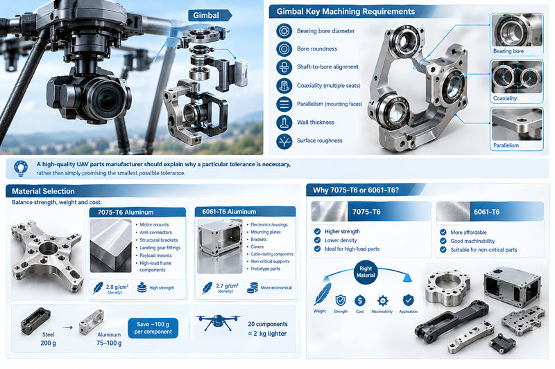
- bearing bore diameter;
- bore roundness;
- shaft-to-bore alignment;
- coaxiality between multiple bearing seats;
- parallelism between mounting faces;
- wall thickness;
- surface roughness at moving interfaces.
This is why a high-quality custom UAV parts manufacturer should be able to explain why a particular tolerance is necessary, rather than simply promising the smallest possible tolerance.
Material selection is one of the biggest decisions in UAV component manufacturing because every gram matters, but reducing weight blindly is not engineering.
The objective is normally to achieve the required strength and stiffness at the lowest practical mass and cost.
For many UAV structural parts, 7075-T6 aluminum is an attractive choice because it combines relatively low density with high strength.
It is commonly considered for:
- motor mounts;
- arm connectors;
- structural brackets;
- landing gear fittings;
- payload mounts;
- high-load frame components.
A typical density is around 2.8 g/cm³, which is dramatically lower than steel at roughly 7.8 g/cm³.
That difference becomes significant when dozens of components are distributed throughout an aircraft.
For example, imagine replacing a 200 g steel bracket with a 75–100 g machined aluminum bracket while maintaining the required structural performance. Saving 100 g from one component may not sound impressive, but if similar reductions are achieved across 20 components, the UAV could potentially remove around 2 kg of structural mass.
However, 7075-T6 is not automatically the best answer.
It can be more expensive than 6061, and its machining behavior, corrosion considerations and surface-treatment requirements need to be considered during design.
6061-T6 is often a more economical option for components where extreme strength is unnecessary.
I would consider it for:
- electronics housings;
- mounting plates;
- brackets;
- covers;
- cable-routing components;
- non-critical structural supports;
- prototype parts.
For a prototype UAV program, 6061-T6 can make considerable commercial sense because the goal is often to validate geometry and assembly before moving to a production material.
There is little value in spending heavily on a premium material for a component that will be redesigned after the first flight test.
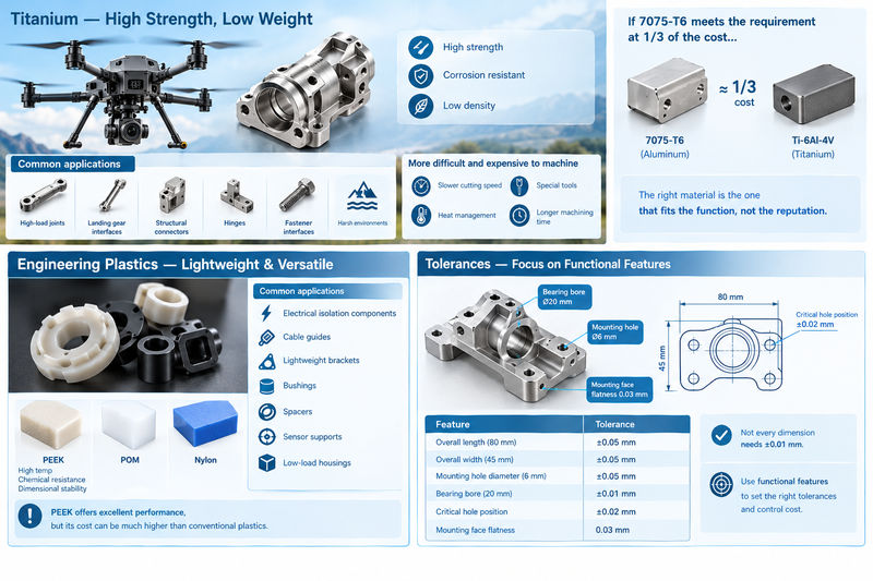
Titanium, particularly Ti-6Al-4V, becomes interesting when the component needs very high strength, corrosion resistance and relatively low mass.
It is commonly considered for:
- high-load joints;
- landing gear interfaces;
- structural connectors;
- hinges;
- high-strength fastener interfaces;
- components exposed to demanding environments.
But titanium should not be selected simply because it sounds more “aerospace.”
It is more difficult and expensive to machine than aluminum. Cutting speed, tool selection, heat management and machining time can all increase.
If a 7075-T6 component satisfies the actual structural requirement at one-third of the manufacturing cost, titanium may not provide any meaningful purchasing advantage.
This is exactly where an experienced CNC supplier should participate in the engineering discussion.
Not every UAV component should be metal.
PEEK, POM, nylon and other engineering plastics can be useful for:
- electrical isolation components;
- cable guides;
- lightweight brackets;
- bushings;
- spacers;
- sensor supports;
- low-load housings.
PEEK is particularly interesting when temperature resistance, chemical resistance and dimensional stability are important, although its raw material and machining cost can be significantly higher than conventional plastics.
The correct material is therefore determined by the component’s function, not by the material’s reputation.
A common purchasing mistake is to put “±0.01 mm” on every dimension.
That is usually unnecessary and can increase machining cost without improving UAV performance.
A better approach is to identify the functional features first.
Consider a simplified UAV bracket:
- Overall length: 80 mm
- Overall width: 45 mm
- Mounting hole diameter: 6 mm
- Bearing bore: 20 mm
- Critical hole position: ±0.02 mm
- Mounting face flatness: 0.03 mm
- General dimensions: ±0.05 mm
There is no reason for the 80 mm outside length to necessarily have the same tolerance as the bearing bore.
If the bearing interface controls motion, that feature deserves more attention.
If the outside edge has 0.3 mm of assembly clearance, tightening its tolerance to ±0.01 mm simply increases cost.
This is where GD&T becomes more valuable than blanket dimensional tolerances.
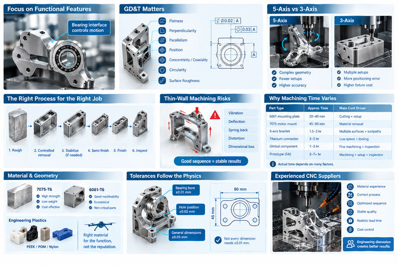
For UAV components, several geometric characteristics can matter more than ordinary dimensions:
| Feature | Why It Matters |
|---|---|
| Flatness | Prevents rocking, distortion and uneven mounting |
| Perpendicularity | Controls motor, shaft and bearing alignment |
| Parallelism | Important for multi-surface assemblies |
| Position | Controls bolt patterns and component interfaces |
| Concentricity/Coaxiality | Important for rotating components |
| Circularity | Important for bearing and shaft interfaces |
| Surface Roughness | Affects seals, bearings and sliding interfaces |
Some current UAV machining specifications list values such as sub-0.01 mm perpendicularity or coaxiality for selected critical features, while general dimensions may be allowed substantially more tolerance.
The important point is not that every UAV component needs those numbers.
The important point is that the tolerance should follow the physics of the component.
5-axis machining is particularly useful for UAV components with:
- angled mounting surfaces;
- complex curved structures;
- deep pockets;
- multiple intersecting faces;
- lightweight lattice-like geometry;
- difficult-to-reach features.
A 3-axis machine may require multiple setups to produce a complicated UAV bracket.
Every additional setup introduces another opportunity for:
- datum transfer errors;
- accumulated positioning error;
- setup time;
- fixture cost;
- inconsistent orientation.
A well-planned 5-axis process can machine several critical surfaces in fewer setups.
That does not mean 5-axis machining is always cheaper.
For a simple flat 7075 plate with four holes, 3-axis machining may be considerably more economical. The correct machine is the one that produces the required geometry with the fewest unnecessary operations.
This is where the difference between ordinary CNC machining and experienced aerospace-style machining becomes obvious.
Many UAV components are designed to remove material aggressively.
A 100 mm × 80 mm × 25 mm aluminum block may become a finished component weighing only 60–100 g after deep pocketing.
The problem is that removing 70–80% of the original material can release internal stress and make thin sections move during machining.
Suppose a UAV bracket starts as a thick 7075 plate.
The machining process removes large pockets from both sides, leaving walls only 1.0–1.5 mm thick.
If the cutting sequence is poorly designed, the wall can:
- vibrate during cutting;
- deflect away from the tool;
- spring back after the cutter leaves;
- distort after the part is released;
- lose dimensional stability during subsequent finishing.
This is why the machining sequence matters almost as much as the machine’s nominal accuracy.
A sensible approach can involve:
- rough machining;
- controlled material removal;
- stress-relief or stabilization where appropriate;
- semi-finishing;
- finishing;
- final inspection.
Some UAV machining suppliers specifically identify thin-wall pocketing and vibration control as important production techniques for lightweight drone structures.
When I compare quotations, I do not compare only the supplier’s unit price.
I ask why the machining time is what it is.
For example:
| Process | Approx. Time Example | Main Cost Driver |
|---|---|---|
| Simple 6061 mounting plate | 20–40 min | Cutting + setup |
| Pocketed 7075 motor mount | 45–90 min | Material removal |
| Complex 5-axis bracket | 1.5–3 hr | Multiple surfaces + toolpaths |
| Titanium structural connector | 2–5 hr | Low cutting speed + tooling |
| Precision gimbal component | 1–3 hr | Fine machining + inspection |
| Prototype with first-article inspection | 2–7+ hr total process | Machining + setup + inspection |
These are planning examples rather than universal production times. Actual time depends heavily on part size, stock condition, machine, toolpath, tolerance, material, quantity and inspection requirements.
The cheapest quotation is sometimes based on an unrealistic machining assumption.
A supplier quoting 30 minutes for a component that realistically requires two hours may eventually compensate through quality problems, delayed delivery or a revised quotation.
Surface treatment should not be selected at the end simply because the drawing says “black.”
For aluminum UAV components, anodizing may improve corrosion resistance and surface durability, while hard anodizing can provide a harder surface for wear-prone applications.
For example:
| Requirement | Potential Finish |
|---|---|
| Appearance | Clear or color anodizing |
| General corrosion resistance | Anodizing |
| Higher wear resistance | Hard anodizing |
| Stainless corrosion protection | Passivation |
| Low-friction interface | Application-specific coating |
| Improved cosmetic uniformity | Bead blasting + anodizing |
The dimensional effect of finishing also needs consideration.
If a precision bore is anodized, the coating thickness can affect the final fit. Therefore, critical dimensions should be designed with the complete manufacturing route in mind rather than machining the nominal dimension and applying the finish afterward without compensation.
This is probably the area where I would challenge a supplier most strongly.
A supplier saying “we inspect 100% of the parts” is not enough.
I want to know:
What did you inspect, with what equipment, against which datum, and where is the record?
For complex UAV components, a Coordinate Measuring Machine can verify relationships that are difficult to establish reliably with handheld instruments. custom UAV parts
A CMM can be used to inspect:
- hole position;
- bore diameter;
- flatness;
- perpendicularity;
- profile;
- distances between datums;
- multiple-axis relationships.
For a gimbal bracket, for example, checking two bearing bores independently is not enough.
The more important measurement may be the relationship between those two bores.
If both bores are individually within diameter tolerance but their axes are misaligned, the assembly can still experience unwanted resistance or play.
That is why the inspection plan should reflect the actual functional requirement.
For a new UAV component, the first manufactured part provides an opportunity to verify the entire manufacturing process.
The supplier should be able to demonstrate that:
- the correct drawing revision was used;
- the correct raw material was used;
- critical dimensions were measured;
- special processes were controlled;
- inspection equipment was calibrated;
- nonconforming features were identified and corrected.
Aerospace-oriented suppliers commonly emphasize FAI, material traceability and configuration control because the documentation behind a part can be as important as the dimensional result itself.
Suppose two aluminum bars look identical.
One has complete material certification and heat-lot information.
The other comes from an unknown stock source.
For a prototype used only for bench testing, the purchasing decision may be different.
For production flight hardware, traceability becomes much more important.
A professional procurement package may include:
- material certificate;
- heat or lot number;
- inspection report;
- dimensional report;
- surface-treatment certificate where required;
- first-article documentation;
- drawing revision;
- batch identification.
This allows the manufacturer and customer to trace the component back through the production process. custom UAV parts
If I were qualifying a new supplier for a UAV program, I would not select the manufacturer based on the lowest CNC price.
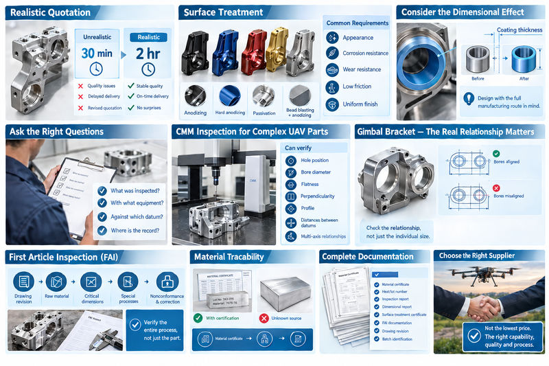
I would use a checklist similar to this:
| Evaluation Item | What I Would Ask |
|---|---|
| Material | Can you provide material certificates and lot traceability? |
| Engineering | Can your engineer review the drawing before production? |
| Machining | Which operations will be 3-axis, 4-axis or 5-axis? |
| Tolerance | Which features are actually critical to assembly? |
| GD&T | Can you inspect geometric tolerances, not just dimensions? |
| Surface Finish | How will finishing affect critical dimensions? |
| Inspection | Can you provide CMM reports? |
| Prototype | Can you manufacture one or a small batch before mass production? |
| Production | How will you maintain consistency between batches? |
| Documentation | Can you provide inspection and material records? |
| Lead Time | Is the quoted lead time based on real machine capacity? |
| Packaging | How will precision components be protected during transportation? |
The best supplier is not necessarily the factory with the smallest tolerance claim.
It is the factory that understands which tolerances actually matter, chooses an appropriate manufacturing route, controls the material and process, and can prove the final part meets the drawing.
Consider a hypothetical 7075-T6 motor mount measuring approximately 95 mm × 70 mm × 18 mm.
The design requires:
- four motor mounting holes;
- one central shaft clearance;
- multiple weight-reduction pockets;
- a flat motor interface;
- attachment holes connecting the mount to the UAV arm;
- black hard anodizing.
A poor manufacturing approach would simply load the model into a CNC machine and start removing material.
A better process would look like this:
Verify the 7075-T6 material and leave sufficient machining allowance.
Identify the primary mounting surface and critical centerline before machining the secondary features.
Remove the majority of the material while leaving controlled stock for finishing.
Stabilize the geometry and prepare critical surfaces for final machining.
Finish the mounting face, hole pattern, bores and other critical features.
Check hole positions, flatness, perpendicularity and other drawing requirements.
Apply the specified anodizing process while accounting for critical dimensional requirements.
Verify the finished component and compare the final measurements with the drawing requirements.
Record the part identification and inspection information and package the component to prevent scratches, deformation and contamination during transportation.
This process may cost more than machining a generic aluminum bracket.
But if the component is going onto a UAV carrying an expensive camera, LiDAR system, communication payload or other flight hardware, the cost of preventing a repeat manufacturing problem can be much lower than the cost of replacing an entire assembly.
For a custom UAV project, Xavier’s role should not simply be to convert a customer’s CAD file into a CNC program.
The more useful approach is to treat the component as part of the aircraft system.
From the initial drawing review, the focus should be placed on material selection, machinability, structural geometry, critical interfaces, tolerances, surface treatment and inspection requirements.
Xavier can support the manufacture of custom CNC components in materials including 7075 aluminum, 6061 aluminum, stainless steel, titanium, brass, copper, alloy steel and engineering plastics, depending on the requirements of the application.
For UAV programs, this can include motor mounts, structural brackets, arm connectors, gimbal components, sensor housings, landing-gear components, precision shafts, mounting plates and other custom-machined hardware.
The most important principle is simple:
A UAV part should not be manufactured to the smallest possible tolerance. It should be manufactured to the right tolerance, using the right material, the right machining process and the right inspection method.
For procurement teams, this approach makes quotations easier to compare and reduces the risk of discovering manufacturing problems only after the parts arrive.
For engineering teams, it creates a more practical path from CAD design to prototype, flight testing and repeat production.
And for the UAV itself, the result is what matters most: a component that fits correctly, weighs what it should, survives its intended operating environment and performs consistently from one production batch to the next.
We are an integrated CNC machining manufacturer and trading company specializing in CNC contract manufacturing and the precision machining of various metal parts. We also provide CNC anodizing surface finishing, CNC electroless nickel surface finishing, and CNC passivation surface finishing to meet different requirements for corrosion resistance, appearance, and functional performance.
As a CNC anodizing surface finishing manufacturer, we can handle both prototype and volume production requirements. We offer CNC electroless nickel surface finishing services for customers requiring consistent and reliable surface protection, and you can contact us for CNC passivation surface finishing pricing based on your part specifications and order volume.
Some of the images and text in this article are collected and compiled from the internet. If there is anything inappropriate, please contact us for processing.