
Aluminum 6061-T6 Drone Parts Machining: Materials, Precision, Design, and Manufacturing Guide
Aluminum 6061-T6 is one of the most practical materials for CNC-machined drone components because it combines low density, useful mechanical strength, good machinability, corrosion resistance, and reliable anodizing performance. For UAV manufacturers, the challenge is not simply machining aluminum into the required shape. It is producing lightweight parts that maintain motor alignment, resist vibration, accommodate fasteners correctly, and remain dimensionally consistent after surface finishing.
For procurement engineers, mechanical designers, and drone manufacturers, five topics deserve particular attention: material properties and component selection, CNC machining strategies, lightweight structural design, tolerances and inspection, and surface finishing with cost control. These are the areas that most directly affect component performance, manufacturing cost, and assembly reliability.
Five Key Topics to Understand Before Machining 6061-T6 Drone Parts
- 6061-T6 material properties and alloy selection: Strength, weight, corrosion resistance, machinability, and when to consider 7075-T6 instead.
- CNC machining processes and toolpath strategy: Milling, turning, multi-axis machining, workholding, and thin-wall distortion control.
- Lightweight drone component design: Motor mounts, frame plates, camera brackets, gimbal housings, and structural weight reduction.
- Machining tolerances and quality inspection: Hole-position accuracy, flatness, bearing fits, vibration-related alignment, and dimensional verification.
- Surface finishing, manufacturing cost, and supplier selection: Anodizing, coating allowances, batch consistency, lead time, and the information needed for a reliable quotation.
1. Aluminum 6061-T6 Material Properties: Why It Works for Drone Parts
1.1 Mechanical properties that matter in UAV manufacturing
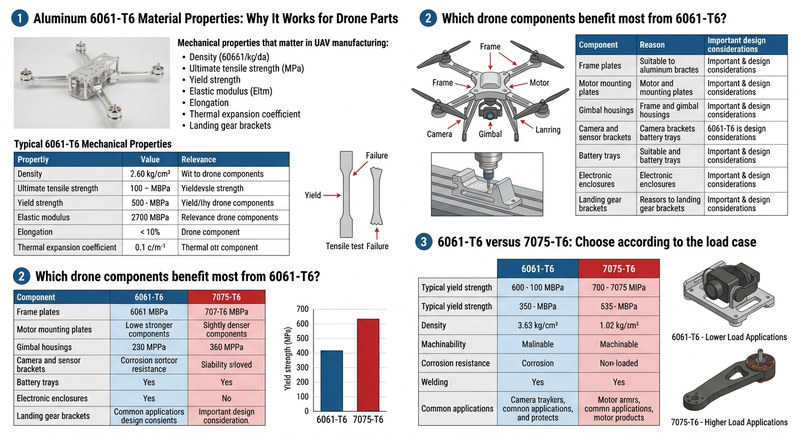
Aluminum 6061-T6 is a precipitation-hardened aluminum-magnesium-silicon alloy. The T6 temper indicates that the material has undergone solution heat treatment followed by artificial aging to achieve its specified mechanical properties. For drone manufacturers, this combination provides a useful balance of strength, low weight, corrosion resistance, and machinability.
Typical room-temperature properties are shown below. Actual values depend on product form, thickness, material specification, and supplier certification.
| Property | Typical 6061-T6 value | Relevance to drone components |
|---|---|---|
| Density | 2.70 g/cm³ | Helps keep structural components lightweight |
| Ultimate tensile strength | 310 MPa | Indicates resistance to tensile failure |
| Yield strength | 276 MPa | Helps determine allowable working loads |
| Elastic modulus | 68.9 GPa | Influences stiffness and deflection |
| Elongation | Approximately 12% | Indicates some capacity for plastic deformation |
| Thermal expansion coefficient | Approximately 23.6 µm/m·°C | Matters for dimensional changes with temperature |
These are representative values, not guaranteed design allowables. Structural calculations should use the governing material specification, certified material test reports, and appropriate design factors.
1.2 Which drone components benefit most from 6061-T6?
6061-T6 is particularly attractive for components that need accurate interfaces, good corrosion resistance, and repeatable surface finishing without the expense of a higher-strength alloy.
| Drone component | Why 6061-T6 is suitable | Important design consideration |
|---|---|---|
| Frame plates | Easy to machine into lightweight profiles and pockets | Preserve stiffness around arm joints |
| Motor mounting plates | Supports precise mounting-hole patterns | Control face flatness and hole position |
| Gimbal housings | Suitable for accurately machined bearing and pivot features | Maintain perpendicularity between axes |
| Camera and sensor brackets | Provides a stable mounting platform | Minimize deflection and vibration transmission |
| Battery trays | Lightweight and easy to customize | Avoid unnecessary material removal around fasteners |
| Electronic enclosures | Good machinability and anodizing options | Account for thermal management and connector clearances |
| Landing gear brackets | Suitable for many moderate-load applications | Check impact loads and fatigue requirements |
For example, a 100 g aluminum bracket has a volume of approximately 37.0 cm³ when made from 6061-T6. The same volume of steel at a density of 7.85 g/cm³ would weigh about 290 g. This illustrates the potential mass advantage of aluminum, although an actual bracket’s geometry and required stiffness may differ between materials.
1.3 6061-T6 versus 7075-T6: Choose according to the load case
A common purchasing mistake is assuming that the strongest available aluminum is automatically the best material for every drone part. The correct selection depends on loading, fatigue life, geometry, environmental exposure, and budget.
| Factor | 6061-T6 | 7075-T6 |
|---|---|---|
| Typical yield strength | Approximately 276 MPa | Approximately 503 MPa |
| Density | Approximately 2.70 g/cm³ | Approximately 2.81 g/cm³ |
| Machinability | Excellent | Very good |
| Corrosion resistance | Generally good | More dependent on protection and environment |
| Welding | Generally more suitable | Fusion welding is generally avoided |
| Common applications | Housings, trays, brackets, general structures | Highly loaded clamps, arms, and structural fittings |
7075-T6 can be advantageous where higher strength permits a lighter or more compact design. However, switching alloys does not automatically improve fatigue life: notches, surface defects, residual stress, fastener preload, and load direction still matter.
For a camera enclosure or electronics tray, 6061-T6 may offer the better overall value. For a highly loaded motor clamp or racing drone arm, 7075-T6 deserves closer evaluation. The final choice should follow engineering calculations and the actual flight-load spectrum, rather than material strength alone.
2. CNC Machining Processes and Toolpath Strategies for 6061-T6 Drone Parts
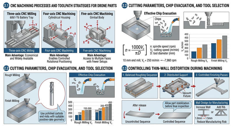
2.1 CNC milling, turning, and five-axis machining
CNC milling is the primary process for frame plates, motor mounts, gimbal housings, mounting brackets, and complex aluminum enclosures. CNC turning is better suited to cylindrical components such as spacers, shafts, bushings, and precision standoffs.
Five-axis machining becomes valuable when several mounting faces, angled holes, curved surfaces, or intersecting features must maintain accurate relationships. Completing more features in one setup can reduce cumulative positioning error and shorten handling time.
| Manufacturing method | Best suited components | Main advantage | Main limitation |
|---|---|---|---|
| Three-axis CNC milling | Flat plates, trays, simple brackets | Economical and widely available | Complex features may require multiple setups |
| Four-axis CNC machining | Radial features, cylindrical housings | Enables controlled rotational positioning | Fixture and programming complexity |
| Five-axis CNC machining | Gimbal bodies, angled mounts, complex frames | Access to multiple faces with fewer setups | Higher machine and programming costs |
| CNC turning | Shafts, bushings, spacers | Efficient cylindrical accuracy | Limited suitability for complex prismatic geometry |
The right process is not necessarily the most advanced machine. A flat 6061-T6 battery tray may be produced economically on a three-axis machining center, while a gimbal housing with two intersecting bearing axes may justify five-axis machining.
2.2 Cutting parameters, chip evacuation, and tool selection
6061-T6 is generally easy to machine, but it can still produce poor results when cutting tools are dull, chips are recut, or cutting conditions generate excessive heat.
Polished carbide end mills with suitable positive-rake geometry are commonly used. Effective chip evacuation is especially important in deep pockets, narrow slots, and enclosed cavities. Flood coolant or minimum-quantity lubrication may be appropriate depending on the machine, tooling, material, and surface-finish requirements.
For a preliminary machining plan, consider the following illustrative ranges. These are starting points for process development, not universal production settings.
| Operation | Illustrative cutting approach | Main objective |
|---|---|---|
| Rough milling | Approximately 150–300 m/min cutting speed | Remove bulk material efficiently |
| Finish milling | Approximately 200–450 m/min, subject to tool limits | Achieve accurate dimensions and surface finish |
| Slotting | Reduce engagement and adjust feed to prevent chip packing | Avoid tool deflection and recutting |
| Deep-pocket milling | Use staged depth passes and reliable chip evacuation | Control heat and tool loading |
| Final wall finishing | Use sharp tools and light, consistent passes | Minimize burrs and dimensional distortion |
Actual spindle speed depends on tool diameter. Cutting speed is converted to spindle speed using:
[ n=\frac{1000V_c}{\pi D} ]
where (n) is spindle speed in rpm, (V_c) is cutting speed in m/min, and (D) is tool diameter in mm.
For example, a 10 mm end mill running at a cutting speed of 250 m/min requires approximately 7,960 rpm. Feed rate must then be calculated from the number of cutting edges, spindle speed, and feed per tooth.
A supplier should validate these settings through test cuts, toolmaker recommendations, machine capability, and the required dimensional and surface-finish results.
2.3 Controlling thin-wall distortion during machining
Thin-wall distortion is one of the most important manufacturing challenges for lightweight aluminum drone components. A frame plate may appear perfectly flat while clamped but spring out of shape after release because the workholding force and material-removal sequence have redistributed stresses.
Consider a 120 × 80 mm frame plate with several large pockets and a nominal wall thickness of 1.0 mm. If one side is machined almost completely before the opposite side is relieved, the remaining structure can deflect or twist.
A more reliable process may include:
- Roughing both sides in a balanced sequence to avoid excessive one-sided material removal.
- Leaving finishing stock on critical mounting faces and thin walls.
- Using soft jaws, vacuum fixtures, or distributed support where appropriate.
- Machining thin sections with controlled radial engagement and light finishing passes.
- Allowing the part to stabilize before final machining and inspection when the geometry or material condition warrants it.
- Measuring flatness after unclamping, not only while the component remains in the fixture.
Wall thickness must be designed around the part’s span, unsupported length, load path, and available workholding. A 1.0 mm wall may be practical in one geometry and unsuitable in another. Adding a small rib or increasing a wall to 1.5 mm can sometimes reduce manufacturing risk more effectively than demanding extremely tight tolerances on a flexible structure.
3. Lightweight Design of CNC-Machined Aluminum Drone Components
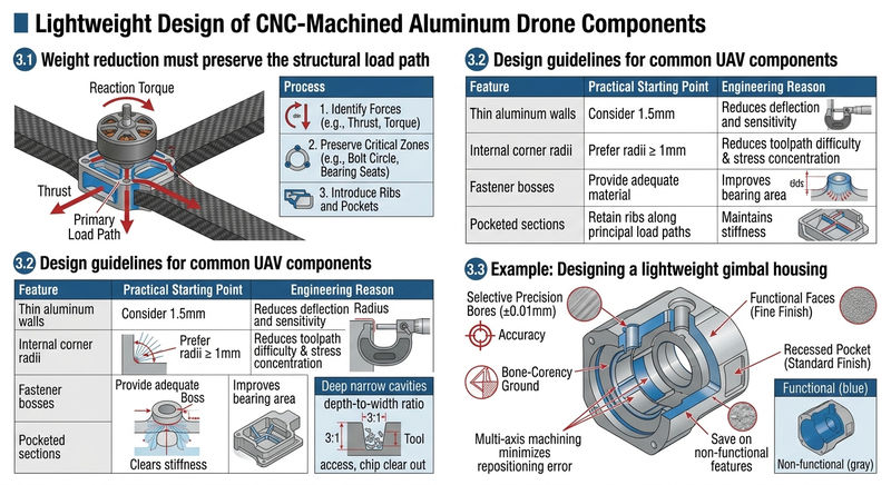
3.1 Weight reduction must preserve the structural load path
The purpose of lightweight CNC machining is not simply to remove as much aluminum as possible. The objective is to remove material from low-stress regions while preserving stiffness and strength around mounting interfaces, fastener holes, bearing seats, and highly loaded joints.
For a drone motor mount, the primary load path transfers motor thrust and reaction torque into the arm or central frame. Removing too much material near the bolt circle can weaken the joint even when the component’s overall weight decreases.
A practical design strategy includes three steps:
- Identify the forces acting on the component, including thrust, torque, vibration, landing impact, and payload loads.
- Preserve material around fasteners, bearing seats, and transitions where stresses concentrate.
- Introduce pockets and ribs only after considering deflection, fatigue, machining access, and minimum practical wall thickness.
Consider a hypothetical motor mount weighing 100 g. If redesigned pockets remove 15 g without compromising stiffness, the mass reduction is 15%. Across four motor mounts, the saving becomes 60 g. Whether this meaningfully improves flight endurance depends on the aircraft’s total mass, power consumption, and flight conditions.
3.2 Design guidelines for common UAV components
| Feature | Practical starting point | Engineering reason |
|---|---|---|
| Thin aluminum walls | Consider 1.5 mm or more where geometry permits | Reduces deflection and machining sensitivity |
| Internal corner radii | Prefer radii of 1 mm or greater when feasible | Reduces toolpath difficulty and sharp internal transitions |
| Fastener bosses | Provide adequate material around holes | Improves bearing area and resistance to local failure |
| Pocketed sections | Retain ribs along principal load paths | Maintains stiffness while reducing mass |
| Deep narrow cavities | Avoid excessive depth-to-width ratios | Improves tool access and chip evacuation |
| Mounting faces | Use clear, accessible datum surfaces | Simplifies machining and inspection |
These values are preliminary design suggestions rather than universal acceptance criteria. Final dimensions must be verified against the component’s load case and geometry.
3.3 Example: Designing a lightweight gimbal housing
A gimbal housing must be light enough to avoid unnecessary payload mass while remaining sufficiently rigid to maintain camera alignment. The critical features are usually the bearing seats, pivot axes, motor interfaces, and mounting surfaces.
Suppose the design uses two bearing bores with a specified diameter tolerance of ±0.01 mm and a perpendicularity requirement between the relevant axes. Machining the bores in separate setups may introduce positioning errors. A suitable multi-axis setup can reduce the number of repositioning operations, although the final accuracy still depends on calibration, tooling, workholding, and inspection.
The design should also distinguish between functional and nonfunctional surfaces. Bearing seats may require a fine finish, while a recessed pocket that does not contact another component may accept a more economical machined finish.
This selective approach avoids paying for precision where it provides no measurable functional benefit.
4. CNC Machining Tolerances, Inspection, and Quality Control
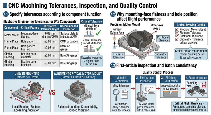
4.1 Specify tolerances according to component function
Not every feature on a drone part needs the same tolerance. Excessively tight specifications can increase machining time, inspection effort, and scrap risk without improving the finished aircraft.
The following values are illustrative engineering targets for discussion with a qualified supplier, not guaranteed manufacturing capabilities or universal industry standards.
| Component | Critical feature | Illustrative tolerance target | Recommended inspection |
|---|---|---|---|
| Motor mount | Mounting-face flatness | 0.02 mm | Surface plate and suitable indicator or CMM |
| Motor mount | Bolt-hole true position | 0.04 mm | CMM or calibrated positional inspection |
| Frame plate | Hole pattern | ±0.02 mm | CMM or appropriate gauges |
| Gimbal housing | Bearing bore diameter | ±0.01 mm | Bore gauge or air gauge |
| Camera bracket | Mounting-face flatness | 0.02 mm | Surface plate or CMM |
| Battery tray | Pocket depth | ±0.10 mm | Depth micrometer |
| Landing gear bracket | General attachment-hole position | ±0.05 mm | CMM or height gauge |
One important distinction: dimensional tolerance, geometric tolerance, and surface roughness describe different characteristics. A hole can have the correct diameter but still be incorrectly positioned. A mounting face can meet its size requirement but fail flatness. Both situations can cause assembly problems.
4.2 Why mounting-face flatness and hole position affect flight performance
Motor mounting surfaces and bolt patterns directly influence assembly alignment. If the mounting face is uneven, tightening the fasteners can introduce local bending or uneven contact pressure. If the hole pattern is displaced, the motor may not sit concentrically or squarely relative to the intended mounting datum.
These errors can contribute to vibration, uneven loading, fastener loosening, and alignment problems. However, vibration also depends on propeller balance, motor condition, bearing quality, frame stiffness, and flight-control tuning. Machining tolerances are only one part of the overall system.
For a precision motor mount, the drawing should clearly identify:
- The primary datum face.
- The location and orientation of the motor axis.
- The bolt-hole pattern and its positional tolerance.
- The required flatness of the mating surface.
- The surface finish of contact interfaces.
- Whether the specified dimensions apply before or after anodizing.
This information helps the supplier establish a suitable machining sequence and inspection method.
4.3 First-article inspection and batch consistency
A part passing inspection once does not prove that an entire production batch will remain consistent. Tool wear, fixture variation, material differences, machine temperature, and finishing operations can all affect the final result.
For a new drone component, a sensible quality-control process includes:
- Material verification: Confirm alloy, temper, and traceability against the purchase specification.
- First-article inspection: Measure critical dimensions, geometric tolerances, hole positions, and relevant surface finishes.
- Finishing verification: Recheck dimensions affected by anodizing or other coatings.
- Batch inspection: Use an agreed sampling plan or full inspection for critical characteristics where required.
- Documentation: Provide inspection results and material certificates according to the purchase order.
For production involving critical flight hardware, the inspection plan should be agreed upon before manufacturing begins. The supplier should understand which dimensions are safety- or function-critical and which can be controlled using general tolerances.
5. Surface Finishing, Manufacturing Cost, and Supplier Selection
5.1 Choosing the right finish for 6061-T6 drone parts
Aluminum drone parts are often exposed to rain, humidity, dust, handling damage, and repeated fastener installation. Surface finishing can improve corrosion protection, wear resistance, and appearance, but the finish must be selected according to the component’s function.
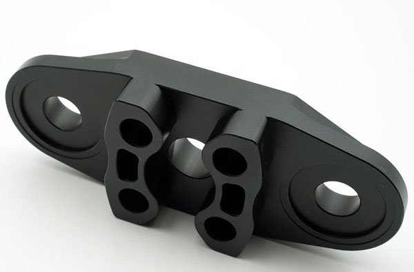
Type II anodizing
General-purpose protection
Suitable for frame plates, brackets, housings, and exposed structural components. It provides corrosion protection and supports dyed finishes such as black, red, and blue.
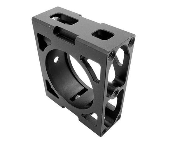
Type III hard anodizing
Wear-resistant interfaces
Worth considering for components exposed to repeated contact, abrasion, or fastener-related wear. The thicker oxide layer requires careful dimensional planning.
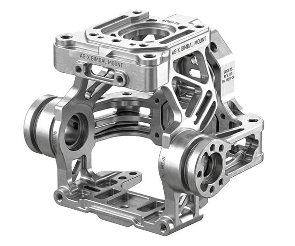
Bead blasting followed by anodizing
Uniform appearance
Helps create a consistent matte surface and reduce the visual prominence of machining marks. Mask critical interfaces when the finishing process could affect fit or finish requirements.
Typical Type II anodizing thickness is approximately 5–25 μm, while Type III hard anodizing is often around 25–75 μm, depending on the specification and application. Actual coating thickness and dimensional growth must be confirmed with the finishing supplier.
5.2 Anodizing allowances: A small detail that can ruin an accurate fit
Anodizing grows an oxide layer from the aluminum surface. Consequently, critical dimensions may change after treatment.
For a simplified example, assume a 5.000 mm bore receives an effective coating thickness of 20 μm on each side. If that entire thickness were to grow inward, the bore diameter would decrease by approximately 0.040 mm. Real dimensional changes depend on the coating process and the proportion of oxide growth into versus outward from the original surface.
For precision drone components, the drawing should specify:
- The required finished dimension after anodizing.
- The coating type and thickness.
- Which holes, threads, and contact faces require masking.
- Whether critical bores will be finish-machined after coating.
- The acceptable color and appearance variation, if applicable.
A bearing seat or precision locating bore should never be treated as an ordinary hole when specifying finishing allowances.
5.3 What determines the cost of CNC-machined drone parts?
The cost of an aluminum drone component is influenced by much more than the price of raw material. Geometry, machine time, workholding, programming, finishing, inspection, and order quantity all contribute.
| Cost factor | Why it matters | Practical cost-control method |
|---|---|---|
| Material size | Oversized stock increases material usage and waste | Select an appropriate stock form |
| Machining time | Deep pockets and complex contours require additional cutting | Simplify nonfunctional geometry |
| Number of setups | Repositioning increases handling and alignment risk | Design accessible datums |
| Tight tolerances | May require additional finishing and inspection | Apply tight tolerances only to critical features |
| Surface finishing | Adds processing, masking, and handling costs | Specify the finish according to actual operating needs |
| Production quantity | Programming and setup costs are distributed across more parts | Plan pilot and production quantities together |
| Inspection requirements | CMM measurement and reporting add time | Agree on the inspection plan before quoting |
For example, a simple flat mounting plate may be relatively inexpensive because it can be cut and drilled with limited setup. A deeply pocketed housing with thin walls, intersecting bores, hard anodizing, and a detailed inspection report may cost substantially more even if both components use the same amount of aluminum.
For budget planning, obtain separate quotations for prototypes and anticipated production volumes rather than assuming that the unit price of a single prototype will predict the final production cost.
5.4 What to include in an RFQ for custom aluminum drone parts
A complete request for quotation helps a manufacturer evaluate both feasibility and cost before machining starts.
Include the following:
- A 3D model in STEP format and a dimensioned 2D engineering drawing.
- The exact material designation: Aluminum 6061-T6.
- Required material certification and traceability.
- Critical dimensions, GD&T requirements, and surface roughness.
- Anodizing type, coating thickness, color, and masking requirements.
- Prototype quantity and expected annual production volume.
- Inspection requirements, including first-article documentation if needed.
- Packaging requirements and the delivery destination.
- Any functional test requirements or assembly interfaces.
If the component is intended for a regulated aerospace application, also identify the applicable material, manufacturing, quality-system, and documentation requirements. A commercial UAV bracket and a flight-critical aerospace component should not automatically be assumed to have the same compliance obligations.
Conclusion: Custom Aluminum 6061-T6 Drone Parts from Xavier
Selecting 6061-T6 for drone parts is a practical decision when the design needs lightweight construction, dependable machinability, corrosion resistance, and flexible finishing options. The best results come from treating material selection, structural design, machining strategy, tolerance control, and anodizing as parts of one manufacturing plan.
At Xavier, we provide CNC machining services for custom metal components, supporting customers who need machined parts produced to their drawings and application requirements. For drone manufacturers developing motor mounts, frame plates, camera brackets, gimbal housings, battery trays, and other precision aluminum components, the goal is to establish the right balance between dimensional accuracy, structural performance, manufacturing efficiency, and cost.
When requesting a quotation, provide your 3D model, engineering drawing, material requirements, surface-finish specifications, and estimated order quantity. This allows the manufacturing team to assess machinability, identify potential design improvements, and recommend a suitable production process.
Explore Xavier CNC machining services to discuss your custom aluminum components and manufacturing requirements.
As an integrated CNC machining manufacturer and trading company, we specialize in CNC contract manufacturing and precision machining of a wide range of metal components. Our finishing capabilities include CNC zinc electroplating surface finishing, CNC chemical conversion coating surface finishing, and CNC passivation surface finishing, helping meet different requirements for corrosion resistance, surface protection, and component appearance.
As an experienced CNC zinc electroplating manufacturer, we provide bulk CNC chemical conversion coating services and competitive CNC passivation pricing for projects of different sizes. Contact us to discuss your specifications and obtain a customized quotation.
Some of the images and text in this article are collected and compiled from the internet. If there is anything inappropriate, please contact us for processing.