
Lightweight UAV Component Design: Materials, Structure, CNC Machining, and Weight Reduction
10 Key Topics Covered in This Article
The following topics reflect recurring engineering and manufacturing concerns in current UAV component design guidance, including lightweight structures, CNC manufacturability, material selection, precision requirements, and inspection.
- Lightweight UAV Design Requirements — Balancing component mass, strength, stiffness, and flight performance.
- Material Selection for Lightweight UAV Components — Comparing 6061-T6 aluminum, 7075-T6 aluminum, titanium, and engineering plastics.
- Structural Optimization and Material Removal — Using pockets, ribs, hollow sections, and topology optimization.
- Thin-Wall Design and CNC Machinability — Controlling deformation, tool access, and machining stability.
- Motor Mounts, Frame Connectors, and Payload Brackets — Designing critical mounting interfaces.
- Vibration Resistance and Fatigue Life — Managing repeated loads and resonance risks.
- CNC Machining Processes and Tolerance Control — Selecting milling, turning, and multi-axis machining.
- Surface Finishing and Corrosion Protection — Choosing anodizing and other finishes according to function.
- Inspection, Testing, and Quality Assurance — Verifying dimensions, weight, assembly fit, and structural performance.
- Manufacturing Cost, DFM, and Supplier Selection — Reducing unnecessary cost without compromising reliability.
1. Lightweight UAV Design Requirements: Balancing Weight, Strength, and Stiffness
Lightweight UAV component design is not simply about removing as much material as possible. Every gram saved must be evaluated against structural strength, stiffness, vibration resistance, service life, and manufacturing cost. A lighter airframe can improve payload capacity and energy efficiency, but a component that bends excessively under motor thrust or landing impact may cause alignment errors, fatigue cracks, or premature failure.
Engineers should begin by defining the component’s maximum operating load, expected service life, allowable mass, operating temperature, and attachment conditions. For example, a motor mount must withstand thrust and torque while maintaining the motor’s mounting-face alignment. A camera bracket may carry a smaller static load but require greater stiffness to prevent image blur.
A useful first calculation is the percentage of mass saved:
[
\text{Weight Reduction}=\frac{m_0-m_1}{m_0}\times100%
]
If a bracket weighs 120 g before redesign and 96 g afterward, the reduction is 20%. However, the new design should only be accepted after checking stress, deflection, fatigue, and assembly fit.
The correct objective is therefore to achieve the lowest practical mass while maintaining the required structural performance, rather than pursuing minimum weight in isolation.
2. Material Selection for Lightweight UAV Components
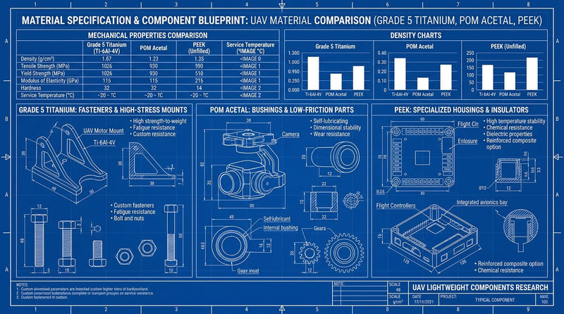
Material selection determines the component’s density, strength, machinability, corrosion resistance, and overall production cost. Aluminum alloys are widely used for CNC-machined UAV brackets, motor mounts, housings, and frame connectors because they combine relatively low density with useful mechanical properties and established machining processes.
| Material | Approx. density | Main advantages | Typical applications |
|---|---|---|---|
| 6061-T6 aluminum | 2.70 g/cm³ | Good machinability, corrosion resistance, versatile finishing | Housings, plates, brackets |
| 7075-T6 aluminum | 2.81 g/cm³ | High strength for its weight | Motor mounts, clamps, structural connectors |
| Grade 5 titanium | 4.43 g/cm³ | High strength, good fatigue and corrosion performance | Highly loaded fasteners and specialized fittings |
| POM (acetal) | 1.40–1.43 g/cm³ | Low friction, dimensional stability, easy machining | Spacers, bushings, non-structural supports |
| PEEK | Approximately 1.30 g/cm³ | High temperature capability and chemical resistance | Insulators and specialized housings |
Density values are approximate; actual properties depend on grade and material condition.
6061-T6 vs. 7075-T6 Aluminum
6061-T6 is a practical choice for general-purpose UAV components where machinability, corrosion resistance, cost, and surface finishing matter. It is particularly suitable for battery trays, electronics housings, sensor brackets, and components that require anodizing.
7075-T6 is often preferable for highly loaded parts such as arm clamps, compact structural lugs, and landing gear connectors. Its higher strength can allow a designer to reduce cross-sectional area, but the actual weight saving depends on stiffness, fatigue, bearing loads, and geometry. It also requires careful corrosion protection and is not normally selected for conventional fusion welding.
Titanium should be reserved for applications where its mechanical or environmental advantages justify its higher material and machining costs. For many UAV parts, selecting the correct aluminum alloy delivers a better overall balance.
3. Structural Optimization and Material Removal
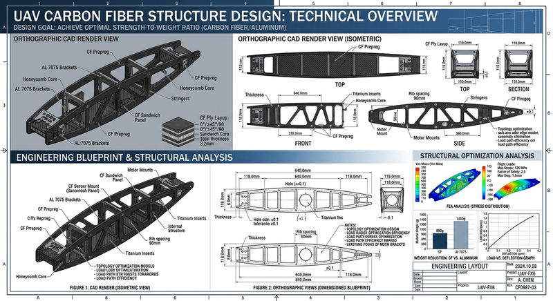
The most effective lightweight UAV designs place material where loads must travel and remove it from regions that contribute relatively little to structural performance. CNC machining makes this approach practical because pockets, ribs, reliefs, and mounting features can be incorporated into a single component.
Pocketing, Ribs, and Hollow Sections
Pocketing removes material from low-stress regions while retaining structural material around mounting holes, threaded bosses, bearing seats, and major load paths. Ribs can increase bending and torsional stiffness without requiring a solid block of material.
For example, a rectangular aluminum mounting plate may initially have a uniform 6 mm thickness. Rather than reducing the entire plate to 4 mm, a designer could retain thicker regions around bolt holes and introduce shallow pockets across less critical areas. This preserves local bearing strength while reducing mass.
The pocket depth, corner radius, and remaining wall thickness must be compatible with the applied loads and available cutting tools. Deep, narrow pockets can increase machining time and tool deflection, potentially eliminating the cost benefits of the lighter design.
Topology Optimization and FEA
Topology optimization uses defined loads, constraints, and design boundaries to identify regions where material can potentially be removed. Finite element analysis (FEA) then evaluates stress distribution, displacement, and other structural responses.
A 2026 study of UAV frame topology optimization investigated mass-reduction constraints of 15%, 20%, and 30%, demonstrating the potential of optimization when followed by structural validation. These values are study-specific results, not guaranteed savings for every UAV component. (U.Porto Journal of Engineering, 2026.)
The optimized geometry must also be reconstructed into a manufacturable design. For CNC production, this means checking cutter access, internal radii, workholding, surface quality, and inspection accessibility before releasing the final drawing.
4. Thin-Wall Design and CNC Machinability
Thin walls can reduce component mass significantly, but they are particularly sensitive to cutting forces, clamping pressure, residual stress, and heat generated during machining. A wall that measures correctly while clamped may spring back after removal from the fixture.
For preliminary design, a wall thickness around 1.5–2.0 mm may be worth evaluating for some small aluminum UAV housings and brackets. It is not a universal minimum: unsupported wall height, material condition, pocket geometry, and load direction can make a thicker wall necessary.
Practical design measures include:
- Use gradual transitions instead of abrupt changes in wall thickness.
- Add ribs near highly loaded mounting points.
- Provide internal corner radii compatible with standard milling cutters.
- Avoid unnecessarily deep, narrow pockets.
- Use suitable support fixtures and reduce cutting forces when finishing thin sections.
For a thin-walled 6061-T6 enclosure, a manufacturer may rough-machine both sides, leave a small finishing allowance, release residual stress where appropriate, and complete the final cuts with reduced cutting loads. This can improve flatness and dimensional consistency.
A design that removes 15% of the mass but doubles machining time may not be commercially attractive. Lightweight geometry must be evaluated alongside machining stability and total production cost.
5. Motor Mounts, Frame Connectors, and Payload Brackets
Different UAV components have different structural priorities. Applying the same lightweighting strategy to every part can create unnecessary engineering risks.
| Component | Main design priority | Important features |
|---|---|---|
| Motor mount | Alignment and thrust-load transfer | Bolt-circle position, mounting-face flatness |
| Arm connector | Clamping strength and fatigue resistance | Bore size, wall thickness, fastener spacing |
| Camera bracket | Stiffness and positional stability | Interface alignment, mounting-face geometry |
| Battery tray | Low mass and secure retention | Fastener locations, edge strength |
| Electronics housing | Protection and thermal management | Wall thickness, cable openings, sealing surfaces |
Fastener and Interface Design
Mounting holes should be positioned relative to functional datums rather than dimensioned through long chains of unrelated measurements. A motor mount may use its primary face as a datum, with the motor pilot and bolt-circle pattern controlled relative to that face.
Threaded holes also require adequate engagement length and edge distance. Removing too much material around a threaded hole can lead to stripped threads or local cracking under repeated loads. For components frequently removed during maintenance, threaded inserts may be appropriate, provided their additional mass and installation requirements are considered.
Locating shoulders, pilots, or dowel pins can improve repeatable assembly when bolt clearance alone does not provide sufficient positioning accuracy.
The design goal is to make each component lightweight without compromising the interfaces that determine how the complete UAV fits together.
6. Vibration Resistance and Fatigue Life
UAV components experience repeated excitation from motors, propellers, aerodynamic forces, and landing events. Even if a bracket survives a single static load, cyclic stress can initiate cracks around holes, sharp corners, thin sections, or abrupt changes in cross-sectional area.
Vibration resistance depends on more than material strength. Component stiffness, mass distribution, mounting conditions, and natural frequency all influence dynamic behavior. If a structural resonance approaches an important operating excitation frequency, vibration amplitudes may increase significantly.
For a simplified single-degree-of-freedom system, the natural frequency is approximately:
[
f_n=\frac{1}{2\pi}\sqrt{\frac{k}{m}}
]
where (k) represents effective stiffness and (m) represents effective mass. Real UAV structures require more complete modal analysis, but this relationship illustrates why removing mass without evaluating stiffness can change vibration behavior.
Designers should use generous fillets around load transitions, avoid unnecessary sharp internal corners, and assess stress concentrations near fasteners. Where the application warrants it, FEA, modal testing, fatigue testing, and vibration testing should be used to validate the finished design.
The required test conditions should reflect the intended UAV, payload, motor operating range, and service environment. No single vibration test or safety factor is appropriate for every component.
7. CNC Machining Processes and Tolerance Control
CNC machining is suitable for UAV components that require accurate mounting interfaces, repeatable dimensions, and flexible production quantities. The best process depends on part geometry, material, quantity, and the features that must be inspected.
| Process | Suitable applications | Manufacturing considerations |
|---|---|---|
| 3-axis CNC milling | Plates, brackets, pockets, housings | Efficient for accessible features |
| 4-axis machining | Components with features around a rotary axis | Reduces repeated repositioning |
| 5-axis CNC machining | Complex brackets and multi-face components | Improves access and datum consistency |
| CNC turning | Shafts, bushings, cylindrical adapters | Controls concentricity and diameter |
| Wire EDM | Selected conductive materials and intricate profiles | Useful for geometries difficult to mill |
Tolerance should be assigned according to function. As an initial drawing guideline, non-critical milled dimensions may use a general tolerance such as ±0.05 mm, while a critical locating feature might require ±0.02 mm or tighter after feasibility review. These are illustrative values, not universal manufacturing guarantees.
A locating bore, bearing seat, or motor interface may need more stringent controls than an external cosmetic profile. Over-tolerancing every dimension increases machining and inspection costs without necessarily improving flight performance.
For critical features, the drawing should identify datums, geometric tolerances, thread specifications, and whether dimensions apply before or after surface treatment.
8. Surface Finishing and Corrosion Protection
Surface finishing affects corrosion resistance, wear, appearance, electrical behavior, and dimensional fit. For aluminum UAV parts, anodizing is a common option, but the correct process depends on the component’s function.
| Finish | Potential benefit | Design consideration |
|---|---|---|
| Type II anodizing | Corrosion protection and color options | Coating changes dimensions and electrical conductivity |
| Type III hard anodizing | Improved wear resistance and a harder surface | Thickness and fit must be controlled |
| Bead blasting | Uniform matte appearance | May change surface texture and appearance |
| Chemical conversion coating | Corrosion protection with selected electrical requirements | Process compatibility and specification matter |
| As-machined finish | Lower finishing cost | Exposed surfaces may need additional protection |
For example, a black-anodized camera bracket may need cosmetic consistency, while a clamping component may prioritize wear resistance. A precision bore or threaded hole may require masking or finishing allowances to preserve the specified fit.
Anodizing is electrically insulating compared with bare aluminum, so grounding or electrical contact points may need masking or another specified treatment. Coating thickness should be considered before final dimensions are established.
For UAVs operating outdoors, near saltwater, or in humid environments, material compatibility and corrosion protection should be reviewed together. When carbon fiber and aluminum are assembled, suitable isolation measures may also be necessary to reduce galvanic corrosion risk.
9. Inspection, Testing, and Quality Assurance
A lightweight UAV component should be inspected against the requirements that determine its performance, not merely against its external appearance. A part can meet its overall dimensions yet still fail during assembly because a mounting face is not flat or a hole pattern is incorrectly positioned.
A practical inspection plan may include:
- Dimensional inspection: Verify critical diameters, thicknesses, hole positions, and geometric tolerances.
- Flatness and alignment: Check mating surfaces and interfaces that control motor, sensor, or bearing alignment.
- Weight verification: Measure actual component mass when it is a design or acceptance requirement.
- Thread inspection: Confirm thread size, condition, engagement, and freedom from burrs.
- Surface inspection: Check coating coverage, scratches, sharp edges, and specified cosmetic areas.
- Functional testing: Perform assembly checks, load tests, vibration tests, or other validation required by the application.
A coordinate measuring machine (CMM) can be useful for complex geometries and critical positional relationships. Calipers, micrometers, gauges, and height gauges may be sufficient for other features, depending on the tolerance and inspection plan.
For example, a batch of 100 motor mounts may require first-article approval, inspection of critical hole positions, and a defined sampling plan for subsequent parts. The inspection frequency should reflect the risk, process capability, and customer’s quality requirements.
Material certificates, inspection reports, and traceability records may also be required for applications with formal quality documentation requirements.
10. Manufacturing Cost, DFM, and Supplier Selection
The most successful lightweight UAV design considers manufacturing from the beginning. A highly complex component may achieve a small additional weight saving but require expensive five-axis machining, specialized fixtures, longer cycle times, and more demanding inspection.
Design for manufacturability (DFM) helps identify these trade-offs before production. A supplier should review the 3D model, engineering drawing, material specification, finishing requirements, tolerances, and order quantity before confirming a quotation.
Consider a hypothetical aluminum UAV bracket weighing 100 g. A redesigned version weighs 85 g, saving 15%. If the redesign also introduces deep pockets, thin unsupported walls, and several difficult-to-inspect features, the unit cost could rise substantially. If a simpler pocket arrangement achieves most of the same weight reduction, it may be the better commercial solution.
When comparing suppliers, evaluate more than the quoted unit price. Review machining capability, material sourcing, surface-treatment control, dimensional inspection, delivery commitments, and the ability to maintain consistency across repeat orders.
For quotation, provide:
- A current STEP model and matching 2D engineering drawing.
- Material grade and temper.
- Required quantity and estimated repeat-order volume.
- Critical dimensions and geometric tolerances.
- Surface finish, masking, and cosmetic requirements.
- Inspection documents and any special testing requirements.
Clear specifications reduce quotation uncertainty and help prevent costly design changes after the first prototype.
Partner with Xavier for Lightweight UAV Component Manufacturing
Lightweight UAV component design requires a practical balance of low mass, structural reliability, precision machining, and production cost. The best results come from coordinating material selection, structural optimization, CNC manufacturing, surface finishing, and inspection rather than treating each stage as an independent task.
Xavier provides CNC machining solutions for custom metal components, including aluminum brackets, structural connectors, precision housings, mounting plates, and other machined parts. From prototype development to repeat production, early drawing review can help identify opportunities to simplify machining, improve assembly accuracy, and reduce unnecessary material removal.
If you are developing a lightweight UAV frame, motor mount, camera bracket, or custom structural component, send Xavier your 3D model, engineering drawing, material requirements, and target quantity. Our team can review the manufacturing requirements and help you evaluate a practical production solution.
Contact Xavier today to discuss your custom CNC-machined UAV components and request a manufacturing quotation.
We are an integrated CNC machining manufacturer and trading supplier, specializing in custom CNC machining services and the production of a wide range of metal components for international customers. Our surface treatment options include CNC electroless nickel plating surface finishing, CNC passivation surface treatment, and CNC chemical conversion coating services, helping customers meet specific requirements for corrosion resistance, durability, and surface quality.
As an experienced CNC electroless nickel plating manufacturer, we provide bulk CNC passivation surface treatment services and competitive CNC chemical conversion coating prices. Contact us to discuss your project specifications, production quantities, and custom metal component requirements.
Some of the images and text in this article are collected and compiled from the internet. If there is anything inappropriate, please contact us for processing.