
1. Cast Aluminum Control Arm Design and Suspension Function
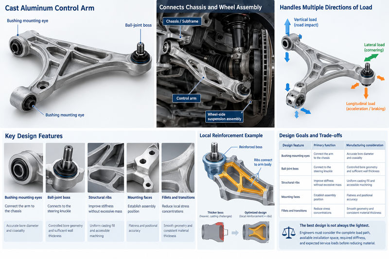
A cast aluminum control arm is a structural suspension component that connects the vehicle chassis or subframe to the wheel-side suspension assembly. It helps control wheel movement while transmitting braking, cornering, acceleration, and road-impact forces through the suspension system.
Unlike a simple aluminum bracket, a control arm must withstand changing loads from multiple directions. Its design usually includes two or more chassis-side mounting points, a ball-joint connection, and a structural body containing ribs, webs, or hollow sections.
The geometry of these features directly affects stiffness, weight, fatigue resistance, and manufacturing cost. For example, increasing the thickness around a ball-joint boss may improve local stiffness, but it can also increase mass and create uneven solidification during casting. A better solution may be to reinforce the boss locally and connect it to the arm body with carefully designed ribs.
| Design feature | Primary function | Manufacturing consideration |
|---|---|---|
| Bushing mounting eyes | Connect the arm to the chassis | Accurate bore diameter and coaxiality |
| Ball-joint boss | Connect the arm to the steering knuckle | Controlled bore geometry and sufficient wall thickness |
| Structural ribs | Improve stiffness without excessive mass | Uniform casting fill and accessible machining |
| Mounting faces | Establish assembly position | Flatness and positional accuracy |
| Fillets and transitions | Reduce local stress concentrations | Smooth geometry and consistent material thickness |
The most effective design is not necessarily the lightest casting. Engineers must consider the complete load path, available installation space, required stiffness, and expected service loads before reducing material.
2. Aluminum Alloys for Cast Control Arms
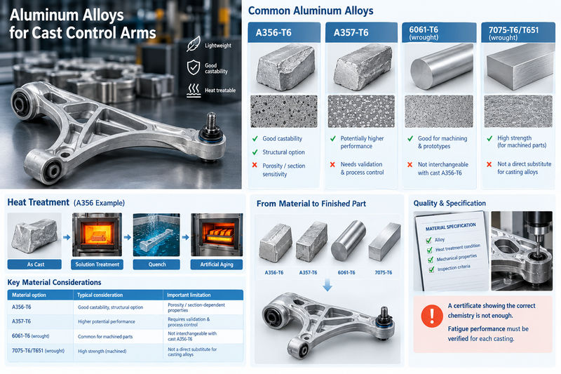
A356 and A357 are important aluminum-silicon-magnesium casting alloys for structural automotive components. Their castability, relatively low density, and response to heat treatment make them potential candidates for suspension arms when the alloy condition and manufacturing process meet the required mechanical specifications.
A356-T6, for example, is commonly considered for structural aluminum castings. The T6 designation indicates solution heat treatment followed by artificial aging. This treatment improves strength compared with the appropriate untreated condition, but the final properties still depend on casting quality, section thickness, heat-treatment control, and test location.
A357 may be selected where a different balance of strength, ductility, and casting performance is required. The correct choice should be based on the component’s design requirements and validated material data rather than alloy designation alone.
| Material option | Typical consideration | Important limitation |
|---|---|---|
| A356-T6 | Established structural casting option with good castability | Porosity and section-dependent properties must be controlled |
| A357-T6 | Potentially higher mechanical performance in suitable casting systems | Requires specification-based validation and process control |
| 6061-T6 wrought aluminum | Common for machined prototypes and billet components | Not interchangeable with cast A356-T6 |
| 7075-T6/T651 wrought aluminum | High strength for suitable machined applications | Not a direct substitute for structural casting alloys |
For a production control arm, the material specification should identify the alloy, heat-treatment condition, mechanical-property requirements, and relevant inspection criteria. A supplier should not treat a certificate showing the correct alloy chemistry as proof that every casting has acceptable fatigue performance.
3. Casting Methods: Low-Pressure Die Casting vs. High-Pressure Die Casting
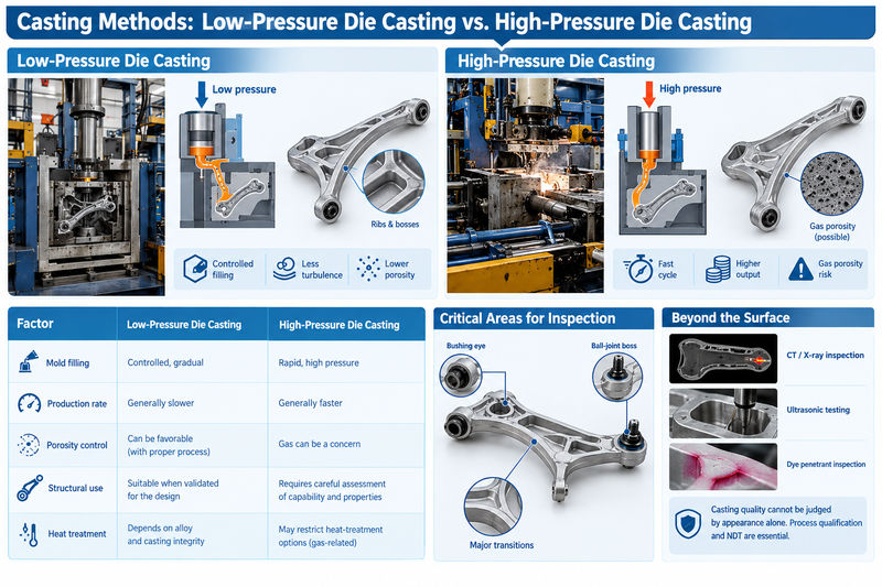
Casting creates the near-net-shape body of a control arm, reducing the amount of material that must be removed by CNC machining. However, the casting process also determines the distribution of porosity, the consistency of the microstructure, and the reliability of load-bearing sections.
Low-pressure die casting is often considered for structural aluminum suspension components because controlled mold filling can help limit turbulence and reduce porosity when the equipment, gating system, melt quality, and process parameters are properly managed. It can also support relatively complex geometries with ribs and mounting bosses.
High-pressure die casting offers rapid cycle times and attractive economics for high-volume production. However, conventional high-pressure die casting can introduce gas-related porosity, which may complicate heat treatment and reduce fatigue reliability in demanding structural applications. Specialized high-integrity processes can change this assessment, so the process name alone should not determine acceptance.
| Factor | Low-pressure die casting | Conventional high-pressure die casting |
|---|---|---|
| Mold filling | Controlled, comparatively gradual filling | Rapid filling under high pressure |
| Production rate | Generally slower | Generally faster |
| Porosity control | Can be favorable with a well-controlled process | Entrapped gas can be a concern |
| Structural suspension use | Suitable when validated for the design | Requires careful assessment of process capability and properties |
| Heat treatment | Depends on alloy and casting integrity | Conventional gas-containing castings may restrict heat-treatment options |
Casting quality should be evaluated in the critical regions around the ball-joint boss, bushing eyes, and major transitions. A visually clean surface cannot reveal every internal defect. Process qualification and appropriate nondestructive testing are therefore essential for safety-critical applications.
4. Cast vs. Forged vs. Billet Aluminum Control Arms
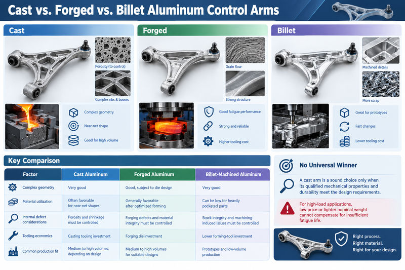
Cast, forged, and billet aluminum control arms can have similar external shapes but different internal structures and manufacturing economics.
Casting allows molten metal to form complex ribs, bosses, and weight-saving profiles. This makes it attractive when the design contains substantial three-dimensional geometry and production volume can justify the tooling. Its main engineering challenge is controlling solidification defects and ensuring consistent mechanical properties.
Forging shapes solid metal under compressive force. Depending on alloy and process design, it can produce favorable grain flow and strong fatigue performance. Forged control arms may be preferable where demanding structural requirements justify the additional tooling and forming operations.
Billet machining starts with wrought stock and removes material to produce the final geometry. It is useful for prototypes, low-volume parts, and designs requiring rapid engineering changes. However, machining a complex arm from a solid billet may generate substantial scrap and require longer machine cycles.
| Comparison | Cast aluminum | Forged aluminum | Billet-machined aluminum |
|---|---|---|---|
| Complex geometry | Very good | Good, subject to die design | Very good |
| Material utilization | Often favorable for near-net shapes | Generally favorable after optimized forming | Can be low for heavily pocketed parts |
| Internal defect considerations | Porosity and shrinkage must be controlled | Forging defects and material integrity must be controlled | Stock integrity and machining-induced issues must be controlled |
| Tooling economics | Casting tooling investment | Forging die investment | Lower forming-tool investment |
| Common production fit | Medium to high volumes, depending on design | Medium to high volumes for suitable designs | Prototypes and low-volume production |
There is no universal winner. A cast arm is a sound choice only when its qualified mechanical properties and durability meet the design requirements. For a high-load application, the lower price or lighter nominal weight of a casting cannot compensate for insufficient fatigue life.
5. CNC Machining of Cast Aluminum Control Arms
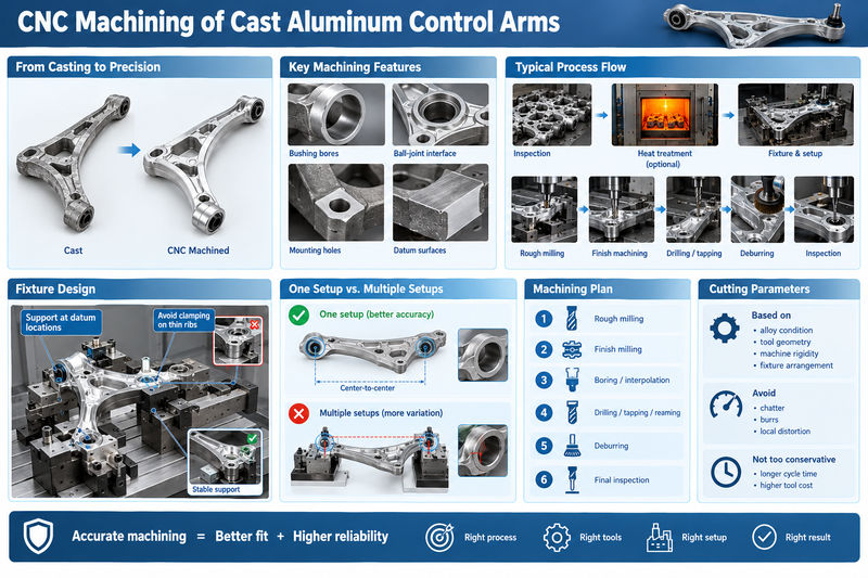
Casting establishes the approximate shape, but CNC machining creates the precise interfaces required for assembly. The most important operations commonly include machining bushing bores, ball-joint interfaces, mounting holes, and datum surfaces.
A typical process begins with casting inspection and, where specified, heat treatment. The casting is then securely located in a fixture, rough-machined to remove excess material, and finish-machined at critical interfaces. The exact sequence depends on the part geometry and whether the component is machined before or after its final heat-treatment stage.
Fixture design is particularly important. A casting may have draft angles, uneven surfaces, and local variations in stock allowance. Clamping directly against a thin rib can distort the part, producing dimensions that change when the fixture is released. Supporting the arm at stable datum locations and distributing clamping force helps reduce this risk.
For example, if two chassis-side bushing bores must maintain a specified center-to-center distance, machining them in a common setup can reduce accumulated positioning error. If the bores are machined in separate setups, fixture location and datum transfer become additional sources of variation.
A practical machining plan may include:
- Rough milling of mounting pads and accessible surfaces.
- Finish milling of datum faces and mounting interfaces.
- Boring or circular interpolation of bushing and ball-joint bores.
- Drilling, tapping, or reaming of specified holes.
- Controlled deburring without damaging functional edges.
- Final dimensional inspection after the part has stabilized.
Cutting parameters should be chosen for the actual alloy condition, tool geometry, machine rigidity, and fixture arrangement. Excessively aggressive cutting can cause chatter, burr formation, or local distortion; overly conservative parameters may increase cycle time and tool cost without improving the finished part.
6. Mechanical Strength, Fatigue Life, and Structural Reliability
A control arm does not experience a single static load throughout its service life. It is subjected to repeated and changing forces from road impacts, braking, acceleration, and cornering. Fatigue resistance is therefore a central design requirement.
Two castings with the same nominal alloy can exhibit different fatigue behavior if their porosity, microstructure, surface condition, or heat treatment differs. Internal pores may act as stress concentrators, while sharp geometric transitions can increase local stress. Machining marks and damage around critical edges can also influence crack initiation.
For this reason, tensile strength alone cannot establish whether a control arm is durable enough. Engineers typically combine material-property data with structural analysis, representative load cases, and component-level validation.
Finite element analysis (FEA) can identify highly stressed regions around mounting eyes, rib junctions, and ball-joint bosses. However, simulation results depend on realistic boundary conditions, material data, and load assumptions. They should be verified through physical testing when required by the product specification.
There is no single fatigue-life figure that applies to every cast aluminum control arm. A valid target depends on vehicle mass, suspension geometry, load spectrum, road conditions, design safety factors, and acceptance criteria. Buyers should request evidence that the proposed design and manufacturing process meet the actual application requirements.
7. Dimensional Tolerances and Suspension Fitment
Dimensional accuracy determines whether a control arm fits the chassis and suspension assembly correctly. Critical characteristics include bore diameter, hole position, mounting-face flatness, and the relationship between the chassis-side pivots and ball-joint center.
The tolerance should be assigned according to function rather than applied uniformly to every feature. A nonfunctional external contour may tolerate a comparatively broad dimensional range, while a precision bore or a mounting interface may require tighter control.
The following values are illustrative machining targets, not universal automotive acceptance standards.
| Feature | Illustrative target | Recommended verification |
|---|---|---|
| Precision-machined bore diameter | ±0.02 mm | Bore gauge or suitable calibrated instrument |
| Hole center position | ±0.05 mm | CMM or dedicated inspection fixture |
| Mounting-face flatness | 0.05 mm | CMM or appropriate surface measurement method |
| Noncritical cast contour | Defined by drawing | Profile gauge, scanner, or CMM as appropriate |
Actual limits must come from the engineering drawing and functional requirements. A tolerance of ±0.02 mm may be achievable on a suitable machined feature, but it should not be promised for every casting or every geometric characteristic without process validation.
Geometric dimensioning and tolerancing (GD&T) helps communicate how features relate to functional datums. A control arm drawing should establish the datum reference framework needed to verify the relative positions of the mounting interfaces and ball-joint connection.
8. Surface Finishing and Corrosion Protection
Cast aluminum control arms may encounter moisture, road salt, stone impacts, and contact with dissimilar metals. Surface protection helps control corrosion, but the finishing method must be compatible with the alloy, design, and service environment.
Shot blasting is often used to remove loose scale and improve surface uniformity before subsequent operations. It is not a substitute for machining critical interfaces, nor does it prove that a casting is free from internal defects.
Conversion coatings and compatible paint or powder-coating systems can provide corrosion protection when properly specified and applied. Anodizing may be appropriate for some aluminum components, but its suitability for a structural suspension arm must be assessed against the alloy, fatigue requirements, coating thickness, and any applicable product specification.
Masking may be necessary to protect precision bores, threaded holes, and electrical or mechanical contact surfaces. Coating buildup on a bore can affect fit, while an unsuitable pretreatment or poorly controlled coating process can undermine corrosion resistance.
The purchase specification should identify the coating system, appearance requirements, thickness where relevant, masked areas, and required corrosion testing. Any coating-related effect on fatigue performance should also be considered for the particular design.
9. Quality Control and Testing
A reliable control arm manufacturing program needs controls for incoming material, casting integrity, heat treatment, machining, and final inspection. No single test can verify every aspect of part quality.
A practical inspection plan may include:
| Inspection stage | Typical checks | Purpose |
|---|---|---|
| Incoming material | Alloy identification and material documentation | Confirm material traceability |
| Casting | Visual examination and specified radiographic or CT inspection | Identify relevant casting defects |
| Heat treatment | Process records, hardness, and specified mechanical tests | Verify the required material condition |
| CNC machining | Bore sizes, positions, datum relationships, and surface condition | Confirm assembly fit |
| Final validation | Specified static, fatigue, or other component tests | Verify performance against design requirements |
X-ray inspection can reveal certain internal discontinuities, while computed tomography (CT) can provide more detailed three-dimensional information where justified. Neither method should be treated as a guarantee of zero defects; detection capability depends on the defect type, size, location, equipment, and inspection procedure.
Coordinate measuring machines (CMMs) are useful for verifying complex dimensional relationships. For production batches, a combination of CMM checks, calibrated gauges, and documented sampling plans can balance inspection efficiency with risk control.
For a safety-critical suspension part, acceptance criteria should be agreed before production begins. Material traceability, process-change control, nonconformance handling, and retention of inspection records are just as important as the initial sample inspection.
10. Manufacturing Cost, Lead Time, and Supplier Selection
The cost of a cast aluminum control arm includes more than the price of the aluminum. Major cost drivers include casting tooling, alloy and melt management, casting yield, heat treatment, CNC machining time, fixture development, inspection, surface finishing, and scrap or rework.
Casting tooling can create a substantial upfront expense, but the cost per part may decrease as production volume increases. Billet machining can reduce the need for casting tooling during early development, although material waste and longer machining cycles may make it less economical at higher volumes.
Consider a hypothetical project requiring 5,000 control arms. If a casting route saves $8 per part in downstream material and machining costs compared with an alternative route, the gross recurring saving would be $40,000. However, if the casting route requires an additional $25,000 in tooling, the simplified difference before inspection, scrap, and other costs would be $15,000 in favor of casting. These figures illustrate the calculation method only; they are not market quotations.
Lead time should be evaluated across the entire manufacturing chain. Tool design, sample casting, heat-treatment qualification, CNC fixture development, dimensional approval, and durability testing can take longer than the machining operation itself.
When evaluating suppliers, request a clear breakdown of the following:
- Alloy and heat-treatment specification.
- Casting method and defect-control plan.
- CNC machining scope and critical tolerances.
- Surface treatment and masking requirements.
- Inspection reports and material traceability.
- Tooling ownership, sample approval, and production lead time.
The best quotation is not necessarily the lowest unit price. A supplier that can explain the manufacturing route, identify critical dimensions, and provide documented quality controls may reduce the total cost of ownership by limiting rework, rejected batches, and assembly problems.
Conclusion: Custom Cast Aluminum Control Arm Manufacturing with Xavier
A successful cast aluminum control arm depends on the combined performance of material selection, casting integrity, heat treatment, CNC machining, and final inspection. The casting must provide a suitable structural foundation, while machining must establish the interfaces and geometric relationships required for correct suspension assembly.
For automotive engineers, product developers, and sourcing teams, the first step is to define the load requirements, alloy specification, critical dimensions, surface protection, and validation plan before comparing manufacturing quotations.
Xavier provides CNC machining services for custom metal components, including precision-machined aluminum parts. For a cast aluminum control arm project, share your 2D drawings or 3D CAD files, material requirements, critical tolerances, surface-finish specifications, and estimated order quantity.
Our team can review the machining requirements and help assess a suitable manufacturing approach for prototypes or production parts. Contact Xavier to discuss your drawings, machining feasibility, inspection requirements, and project quotation.
For safety-critical suspension applications, final material selection, structural design, and durability validation must follow the applicable engineering specifications and vehicle requirements.
As an integrated CNC machining manufacturer and trading company, we specialize in custom CNC machining and contract manufacturing of metal components. Our capabilities cover a wide range of materials and applications, including CNC machining of aluminum, CNC machining of PEEK, and CNC machining of titanium. We manufacture precision components for robotics, aerospace, marine, automotive, medical, and other industrial applications, offering flexible production solutions for prototypes and volume orders.
As a CNC aluminum machining manufacturer, we provide bulk PEEK machining services and offer competitive titanium CNC machining prices. Contact us to discuss your project requirements and receive a tailored quotation.
Some of the images and text in this article are collected and compiled from the internet. If there is anything inappropriate, please contact us for processing.