
What Is CMM Inspection and How Does It Work?
What Is CMM Inspection?
CMM inspection stands for Coordinate Measuring Machine inspection. It is a three-dimensional measurement process used to verify whether a manufactured part matches its engineering drawing, CAD model, dimensional tolerances, and GD&T requirements.
Instead of checking only one dimension at a time with a caliper or micrometer, a CMM records the position of points on a physical part in the X, Y, and Z axes. The inspection software then uses those measured points to calculate features such as distances, diameters, angles, hole locations, flatness, perpendicularity, profile, and true position.
For CNC machining, this is particularly important when a component contains multiple interacting features. A hole may have the correct diameter but still be in the wrong position. A surface may have the correct overall dimensions but be slightly out of parallel. A shaft may have the correct diameter while its axis is not sufficiently concentric or aligned with another feature.
CMM inspection provides numerical evidence of these relationships rather than relying only on individual manual measurements.
| Inspection method | Typical information obtained | Best suited for |
|---|---|---|
| Caliper | Outside/inside dimensions | General dimensions |
| Micrometer | Precise linear/diameter measurement | Shafts, bores, thickness |
| Height gauge | Height and location from a reference | Simple positional checks |
| Pin gauge | Hole size/pass-fail | Repetitive hole inspection |
| CMM | 3D dimensions and geometric relationships | Complex precision parts and GD&T |
| Optical scanner | Large numbers of surface points | Freeform surfaces and complex geometry |
A CMM does not simply answer “What is the size of this part?” It can answer a more important engineering question: “Is this feature located and oriented correctly relative to the other features?”
That distinction makes CMM inspection especially valuable for precision CNC components.
How Does a CMM Work?
A conventional bridge CMM typically consists of a precision table, a moving bridge, a vertical carriage, a probe system, position encoders, and measurement software. The probe moves through the machine’s coordinate system and collects measurement points from the workpiece.
The basic measurement principle is straightforward:
Probe → Contact/scan surface → Record XYZ coordinates → Construct geometry → Compare with nominal requirement → Generate result
For example, suppose a CNC-machined aluminum housing contains a 20.000 mm bore.
The CMM may collect multiple points around the internal cylindrical surface. The software fits those points to calculate the actual cylinder. Instead of simply reporting one manually measured diameter, the CMM can evaluate:
- Bore diameter
- Bore center location
- Cylindricity
- Axis direction
- Position relative to datum features
- Distance between the bore and another feature
This becomes much more useful when the drawing specifies a requirement such as:
Ø20.000 ± 0.010 mm
and a positional tolerance such as:
Position Ø0.020 | A | B | C
The CMM can evaluate the size and the positional relationship within the same coordinate system.
CMM Inspection Process: From Part Setup to Final Measurement
A reliable CMM inspection starts before the probe touches the part. The drawing, tolerances, datums, material, surface condition, and inspection requirements must first be understood.
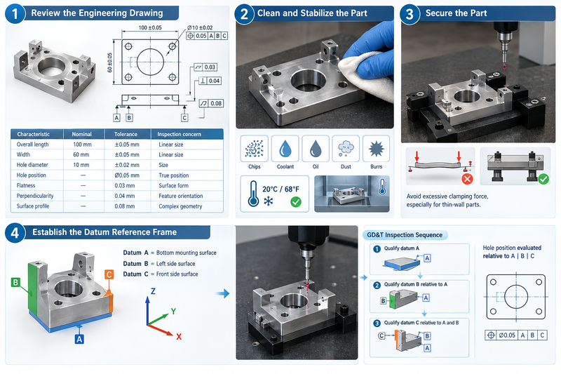
1. Review the Engineering Drawing
The inspector first identifies which characteristics need verification.
For a CNC-machined bracket, the drawing may contain:
| Characteristic | Nominal | Tolerance | Inspection concern |
|---|---|---|---|
| Overall length | 100 mm | ±0.05 mm | Linear size |
| Width | 60 mm | ±0.05 mm | Linear size |
| Hole diameter | 10 mm | ±0.02 mm | Size |
| Hole position | — | Ø0.05 mm | True position |
| Flatness | — | 0.03 mm | Surface form |
| Perpendicularity | — | 0.04 mm | Feature orientation |
| Surface profile | — | 0.08 mm | Complex geometry |
The inspector does not necessarily need to measure every surface randomly. The measurement plan should correspond to the requirements that need to be verified.
2. Clean and Stabilize the Part
Before measurement, chips, coolant, oil, dust, burrs, and other contaminants should be removed.
This sounds simple, but it matters when tolerances are tight.
For example, a small burr around a machined hole can affect the measured diameter or prevent the probe from contacting the intended surface. Temperature can also influence dimensional measurement because both the part and the CMM structure can expand or contract.
For precision inspection, the part should be allowed to reach an appropriate temperature before measurement. A commonly used reference temperature in dimensional metrology is 20°C / 68°F, although the applicable requirement depends on the equipment, drawing, standard, and inspection procedure.
3. Secure the Part
The component must be positioned so that the CMM probe can access the required features.
Fixturing should hold the part securely without unnecessarily deforming it.
This is particularly important for thin-wall CNC components.
For example, imagine a 2 mm thick aluminum cover. If excessive clamping force bends the cover by 0.05 mm, the CMM may accurately measure the deformed part but the result will not represent the component’s intended free-state geometry.
Therefore, measurement accuracy is not determined by the CMM alone. Fixturing, part condition, temperature, probing strategy, and alignment can all affect the result.
4. Establish the Datum Reference Frame
The next step is establishing the coordinate system.
This is one of the most important parts of CMM inspection because a measurement only has meaning relative to an appropriate reference system.
A typical GD&T inspection may use:
- Datum A as the primary reference
- Datum B as the secondary reference
- Datum C as the tertiary reference
These datums establish the coordinate system used to evaluate other features. GD&T Basics demonstrates CMM inspection by qualifying datum A, then evaluating datum B relative to A, and subsequently qualifying datum C.
For example, consider a machined mounting plate:
Datum A = Bottom mounting surface
Datum B = Left side surface
Datum C = Front side surface
The CMM uses these features to establish the part’s orientation and origin. Hole positions can then be evaluated relative to A|B|C rather than simply measuring from an arbitrary physical edge.
This is critical when checking true position, perpendicularity, parallelism, profile, and other GD&T characteristics.
CMM Inspection, Datums, and GD&T
CMM inspection becomes particularly powerful when a drawing uses Geometric Dimensioning and Tolerancing (GD&T).
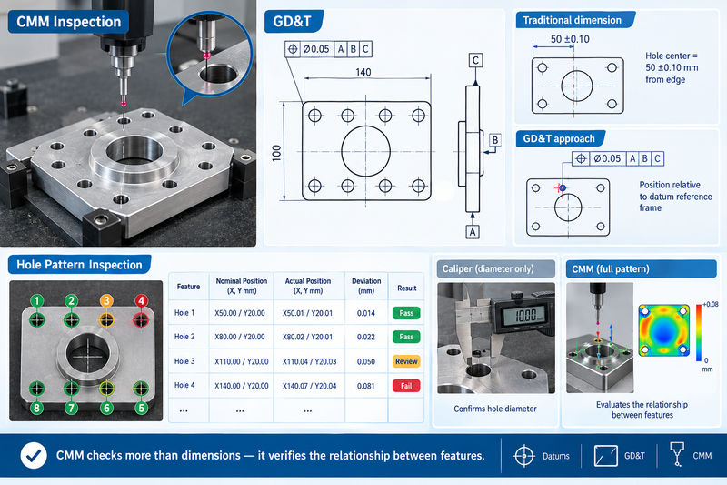
A traditional dimension might specify:
Hole center = 50 ± 0.10 mm from edge
GD&T can instead define the allowable location of that hole relative to a datum reference frame.
For a precision assembly, this distinction can be significant.
Imagine a flange containing eight bolt holes. Each hole has the correct diameter, but several holes are shifted slightly from their intended locations.
A caliper can confirm the hole diameter.
It may be difficult, however, to determine whether the complete hole pattern satisfies the drawing’s positional tolerance.
A CMM can measure the actual centers of all eight holes and calculate their deviations from the theoretical locations.
| Feature | Nominal position | Actual position | Deviation | Result |
|---|---|---|---|---|
| Hole 1 | X50.00 / Y20.00 | X50.01 / Y20.01 | 0.014 mm | Pass |
| Hole 2 | X80.00 / Y20.00 | X80.02 / Y20.01 | 0.022 mm | Pass |
| Hole 3 | X110.00 / Y20.00 | X110.04 / Y20.03 | 0.050 mm | Review |
| Hole 4 | X140.00 / Y20.00 | X140.07 / Y20.04 | 0.081 mm | Fail |
The exact pass/fail result depends on the specified tolerance zone and applicable drawing requirements. The important point is that the CMM evaluates the relationship between features, rather than treating each dimension as an isolated number.
What Can a CMM Measure on CNC Machined Parts?
A CMM can inspect a wide range of dimensional and geometric characteristics.
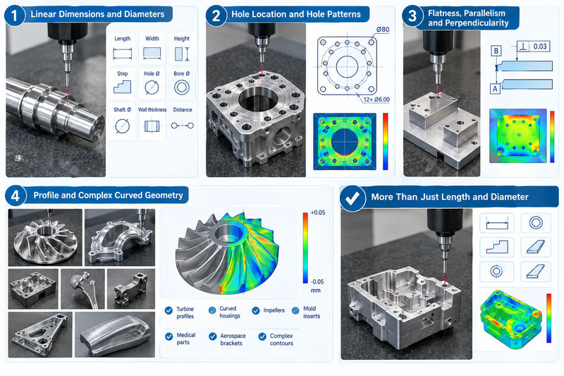
Linear Dimensions and Diameters
Basic dimensional inspection remains one of the most common applications.
A CMM can measure:
- Overall length
- Width
- Height
- Step dimensions
- Hole diameter
- Bore diameter
- Shaft diameter
- Wall thickness
- Distance between features
For example, on a turned stainless-steel shaft, a CMM inspection program could evaluate several shaft diameters and the distance between shoulders in one measurement sequence.
Hole Location and Hole Patterns
Hole patterns are particularly suitable for CMM inspection.
Consider a CNC-machined motor housing with twelve mounting holes. The customer may require:
- Hole diameter: Ø6.00 ±0.02 mm
- Bolt-circle diameter: 80 mm
- Position tolerance: Ø0.05 mm
- Perpendicularity to datum A
The CMM can measure each hole and calculate its actual center, diameter, and relationship to the established datum system.
This provides much more information than simply inserting a Ø6 mm pin gauge.
Flatness, Parallelism, and Perpendicularity
A CMM can also evaluate geometric relationships between surfaces.
Suppose a machined mounting plate has two critical surfaces:
- Datum A: base surface
- Datum B: mounting surface
The drawing might require B to be perpendicular to A within 0.03 mm.
The inspector can measure multiple points across the surfaces and calculate the relevant geometric characteristic.
This is important for components that must maintain alignment after assembly.
Profile and Complex Curved Geometry
CMMs are also useful for complex surfaces that are difficult to verify using conventional gauges.
Examples include:
- Turbine-style profiles
- Curved housings
- Impellers
- Mold inserts
- Medical components
- Aerospace brackets
- Complex milled contours
CMM software can compare measured points against nominal CAD geometry and identify deviations from the intended surface. CMM inspection is therefore useful beyond simple length and diameter measurements.
Types of CMM Used in Precision Manufacturing
Not every CMM looks the same, and the machine type should match the size, geometry, and inspection requirements of the component.
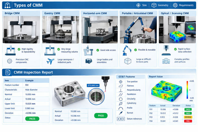
| CMM type | Main advantage | Typical application |
|---|---|---|
| Bridge CMM | High rigidity and repeatability | Precision CNC components |
| Gantry CMM | Very large measuring volume | Large aerospace/industrial parts |
| Horizontal-arm CMM | Good side access | Large bodies and assemblies |
| Portable/articulated CMM | Flexible and movable | Large or difficult-to-move parts |
| Optical/scanning CMM | Rapid surface data collection | Complex profiles and surfaces |
Bridge CMMs are widely used for precision parts because their rigid structure and fixed measuring environment support repeatable measurements. Gantry machines are more appropriate when the component is too large for a conventional bridge machine. Portable systems provide flexibility but can be more sensitive to setup and environmental conditions.
CMM Inspection Reports: What Does the Customer Receive?
One of the major advantages of CMM inspection is that measurement results can be documented in an inspection report.
A typical report may contain:
| Item | Example |
|---|---|
| Feature number | F01 |
| Characteristic | Hole diameter |
| Nominal | 10.000 mm |
| Actual | 10.006 mm |
| Upper limit | 10.020 mm |
| Lower limit | 9.980 mm |
| Deviation | +0.006 mm |
| Status | PASS |
The deviation is generally the difference between the measured value and the nominal value. For example:
Actual = 10.006 mm
Nominal = 10.000 mm
Deviation = +0.006 mm
Because 10.006 mm is between the specified limits of 9.980 and 10.020 mm, this particular dimensional characteristic passes.
For GD&T characteristics, the report may contain additional information such as:
- True position
- Flatness
- Perpendicularity
- Parallelism
- Circularity
- Cylindricity
- Profile
- Runout
- Datum references
The report turns physical measurement into documented dimensional evidence that can be reviewed by engineering, quality, purchasing, and the end customer.
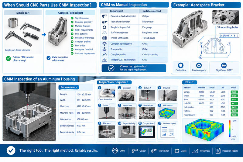
When Should CNC Parts Use CMM Inspection?
CMM inspection is not automatically necessary for every CNC-machined component.
For a simple aluminum spacer with a loose dimensional tolerance, a micrometer or caliper may be sufficient.
CMM inspection becomes much more valuable when the component has:
- Tight dimensional tolerances
- Complex geometry
- Multiple interacting features
- GD&T requirements
- Critical hole patterns
- Tight positional tolerances
- Complex profiles
- First article requirements
- Aerospace or medical applications
- Customer-specific inspection requirements
A practical example is a CNC-machined aerospace bracket.
Suppose the bracket contains 18 mounting holes, several machined reference surfaces, and a profile tolerance. Measuring each diameter with a manual instrument does not fully prove that the hole pattern and surfaces have the required spatial relationships.
A CMM can establish the datum reference frame and evaluate those features within the same coordinate system.
This is why CMM inspection is often selected for first article inspection, precision components, and parts with significant GD&T requirements.
CMM Inspection vs Manual Inspection
CMM inspection does not necessarily replace every conventional measuring instrument.
In a well-organized CNC quality-control process, different tools are used for different characteristics.
For example:
| Requirement | Suitable method |
|---|---|
| General outside dimension | Caliper |
| Tight shaft diameter | Micrometer |
| Simple hole pass/fail | Pin gauge |
| Surface roughness | Roughness tester |
| Thread verification | Thread gauge |
| Complex hole location | CMM |
| True position | CMM |
| Complex profile | CMM/scanning |
| Multiple GD&T relationships | CMM |
The best inspection method is therefore not simply “use the most advanced machine.”
It is to select a measurement method that can reliably verify the actual requirement.
Example: CMM Inspection of a CNC-Machined Aluminum Housing
Consider a 6061-T6 aluminum electronic enclosure with the following requirements:
- Overall length: 120 ±0.05 mm
- Overall width: 80 ±0.05 mm
- Main bore: Ø30 ±0.02 mm
- Four mounting holes: Ø8 ±0.02 mm
- Hole position: Ø0.05 mm
- Bottom flatness: 0.03 mm
- Side-wall perpendicularity: 0.04 mm
A reasonable CMM inspection sequence could be:
Step 1: Clean and stabilize the housing.
Step 2: Secure the component without distorting the thin walls.
Step 3: Qualify datum A from the bottom surface.
Step 4: Establish datum B from the side surface.
Step 5: Establish datum C from the front reference surface.
Step 6: Measure the main bore and calculate its diameter and center.
Step 7: Measure all four mounting holes.
Step 8: Calculate hole positions relative to A|B|C.
Step 9: Measure the bottom surface for flatness.
Step 10: Evaluate side-wall perpendicularity.
Step 11: Compare actual measurements with the drawing requirements.
Step 12: Generate the inspection report.
The resulting report provides a much clearer quality record than simply stating that the component was “inspected.”
What A Good CMM Inspection Cannot Automatically Guarantee
It is important to understand that a CMM is a measurement system, not a magic accuracy generator.
Having a CMM does not automatically mean every measurement is perfect.
Measurement confidence can be affected by:
- CMM calibration
- Probe qualification
- Probe tip size
- Part temperature
- Machine temperature
- Fixturing
- Surface condition
- Probe access
- Alignment strategy
- Number and distribution of measurement points
- Software settings
- Operator/programmer experience
For example, measuring a very small feature with an unsuitable probe can produce a less reliable result even when the CMM itself has excellent specifications.
Similarly, a poorly selected datum alignment can produce a technically precise measurement that does not represent the engineering intent of the drawing.
Therefore, CMM inspection should always be treated as a complete measurement process, not simply as a machine operation.
Why CMM Inspection Matters for CNC Machining
For CNC machining customers, the main value of CMM inspection is not simply obtaining more decimal places.
Its real value is establishing whether critical features have been manufactured in the correct size, position, orientation, and geometric relationship.
For a precision shaft, that may mean verifying diameter and concentricity.
For a CNC housing, it may mean checking bore position and perpendicularity.
For an aerospace bracket, it may mean verifying dozens of dimensions and GD&T characteristics against a common datum reference frame.
For a medical component, it may provide documented evidence that critical geometry conforms to the customer’s drawing.
In other words, CMM inspection connects the CNC machining process with measurable engineering requirements.
Xavier CNC Machining and CMM Inspection
For customers sourcing precision CNC machined parts, dimensional inspection should be considered part of the manufacturing process rather than an afterthought.
At Xavier, our CNC machining approach combines precision manufacturing with appropriate quality-control methods for different part requirements. For components involving tight tolerances, complex geometries, critical hole locations, or GD&T requirements, CMM inspection can provide detailed dimensional verification and a documented inspection record.
The appropriate inspection method depends on the actual drawing, tolerance level, part geometry, material, application, and customer quality requirements. Instead of applying the same inspection method to every component, Xavier can match the inspection approach to the characteristics that matter most for the final application.
For customers ordering prototypes, low-volume precision components, or production CNC parts, a clearly defined inspection plan helps reduce dimensional uncertainty before parts reach assembly.
When your drawing contains critical GD&T characteristics or tight positional requirements, CMM inspection can provide the measurement evidence needed to confirm that the finished CNC part matches the design intent.
We are an integrated CNC machining manufacturer and trading company specializing in CNC outsourcing and the production of various metal parts. Our capabilities include CNC machining stainless steel, CNC machining PEEK, and CNC machining titanium, as well as components for robotics, aerospace, marine, automotive, medical, and other precision applications.
As a CNC machining stainless steel manufacturer, we provide CNC machining PEEK services and can also offer CNC machining titanium pricing. Feel free to contact us for your machining requirements.
Some of the images and text in this article are collected and compiled from the internet. If there is anything inappropriate, please contact us for processing.