
What Is Precision Metal Cutting and How Does It Work?
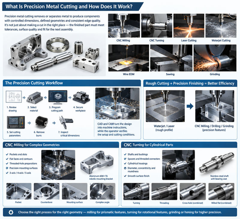
Precision metal cutting is a manufacturing process that removes or separates metal to produce components with controlled dimensions, defined geometries, and consistent edge quality. Depending on the part design, the process may involve CNC milling, CNC turning, laser cutting, abrasive waterjet cutting, wire electrical discharge machining (wire EDM), sawing, or grinding.
The important distinction is that precision metal cutting is not simply about making a cut in the correct location. The finished component must meet dimensional tolerances, maintain the required surface condition, and fit correctly into the next assembly. For example, cutting a stainless steel plate to create a mounting bracket is relatively straightforward, but producing accurate bolt holes, perpendicular edges, and a flat mating surface may require additional machining and inspection.
A typical production workflow includes reviewing the engineering drawing, selecting the material, programming the cutting path, securing the workpiece, establishing cutting parameters, removing burrs, and inspecting critical dimensions. CAD and CAM software translate the part design into machine instructions, while the operator verifies that the setup and cutting conditions suit the actual material.
For manufacturers, the most economical strategy is often to separate rough cutting from precision finishing. A waterjet or laser can create the initial profile, while CNC milling, drilling, or grinding completes the features that require closer dimensional control.
CNC Milling and Turning for Precision Metal Components
CNC milling and turning are particularly useful when a metal component requires three-dimensional geometry rather than a simple flat outline. Although both processes remove material with computer-controlled equipment, they are suited to different part shapes.
CNC Milling for Complex Geometries
During CNC milling, rotating cutting tools remove material from a stationary or controlled-moving workpiece. Milling can produce pockets, slots, flat faces, contours, threaded-hole preparations, and precision mounting surfaces. Three-axis machines are suitable for many prismatic parts, while four-axis and five-axis machines can machine multiple faces and complex angled features with fewer setups.
Consider an aluminum 6061-T6 robotic mounting bracket. Laser cutting may efficiently produce its flat outer profile, but CNC milling is better suited to creating a recessed pocket, a controlled-depth counterbore, and a flat interface for mounting a bearing. Combining these processes can reduce machining time without sacrificing the accuracy of functional features.
CNC Turning for Cylindrical Parts
CNC turning rotates the workpiece against a cutting tool and is commonly used for shafts, bushings, spacers, threaded connectors, and cylindrical housings. Diameter, concentricity, roundness, and surface finish are often more important than the external profile alone.
For instance, a stainless steel shaft with a bearing seat may require a precisely controlled diameter and a smooth surface to prevent excessive clearance or premature wear. If the shaft also contains cross-holes or milled flats, turning can be combined with milling or drilling.
The key is to choose the process according to the critical geometry. Milling is generally preferable for prismatic features, turning for rotational features, and grinding or honing when a particularly fine finish or close dimensional control is necessary.
Laser Cutting vs. Waterjet Cutting vs. Plasma Cutting
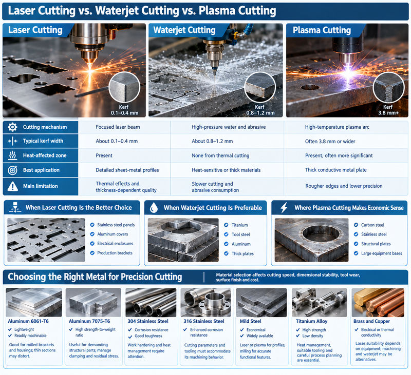
Laser, waterjet, and plasma cutting are common options for producing metal profiles. Their differences in cutting mechanism, kerf width, thermal impact, and operating cost influence which process is most suitable for a particular component.
| Factor | Laser cutting | Abrasive waterjet | Plasma cutting |
|---|---|---|---|
| Cutting mechanism | Focused laser beam | High-pressure water and abrasive | High-temperature plasma arc |
| Typical kerf width | About 0.1–0.4 mm | About 0.8–1.2 mm | Often 3.8 mm or wider |
| Heat-affected zone | Present | None from thermal cutting | Present, often more significant |
| Best application | Detailed sheet-metal profiles | Heat-sensitive or thick materials | Thick conductive metal plate |
| Main limitation | Thermal effects and thickness-dependent quality | Slower cutting and abrasive consumption | Rougher edges and lower precision |
Kerf values are illustrative industry ranges, not guaranteed specifications. Actual results depend on machine capability, material grade, thickness, settings, and cutting-head condition. Reference: Xometry’s sheet-cutting design guide.
When Laser Cutting Is the Better Choice
Fiber laser cutting is well suited to sheet-metal parts with intricate outlines, closely spaced features, and relatively small holes. It is frequently used for stainless steel panels, aluminum covers, electrical enclosures, and production brackets. Its narrow kerf supports efficient material nesting, and nitrogen-assisted cutting can provide clean, oxide-reduced edges on suitable materials.
However, the concentrated heat can produce localized thermal changes, dross, or distortion if cutting parameters and part layout are poorly controlled. Highly reflective metals such as copper also require appropriate laser equipment and settings.
When Waterjet Cutting Is Preferable
Abrasive waterjet cutting removes material using a high-pressure water stream containing abrasive particles. Because it does not rely on a thermal cutting mechanism, it is valuable for titanium, tool steel, aluminum, and other materials where heat-related distortion or metallurgical changes must be avoided.
Waterjet cutting is particularly attractive for thick plates and heat-sensitive parts. Nevertheless, the jet can lag behind the programmed path, producing striations or taper through the material thickness. Slower cutting, suitable nozzle selection, and taper compensation can improve the result.
Where Plasma Cutting Makes Economic Sense
Plasma cutting is commonly used for thick electrically conductive metals, including carbon steel and stainless steel. It offers high productivity for structural plates, large equipment bases, and parts where edge finish requirements are moderate.
For a heavy steel support plate, plasma may be the most economical method for creating the initial blank. If the plate includes precision bearing bores or tightly controlled locating holes, those features can be machined afterward instead of relying on plasma cutting alone.
Choosing the Right Metal for Precision Cutting
Material selection influences cutting speed, dimensional stability, tool wear, surface finish, and final cost. Two parts with identical geometry can require substantially different manufacturing strategies when produced from different alloys.
| Material | Relevant characteristics | Practical cutting considerations |
|---|---|---|
| Aluminum 6061-T6 | Lightweight, readily machinable | Good for milled brackets and housings; thin sections may distort |
| Aluminum 7075-T6 | High strength-to-weight ratio | Useful for demanding structural parts; manage clamping and residual stress |
| 304 stainless steel | Corrosion resistance and good toughness | Work hardening and heat management require attention |
| 316 stainless steel | Enhanced corrosion resistance | Cutting parameters and tooling must accommodate its machining behavior |
| Mild steel | Economical and widely available | Laser or plasma for profiles; milling for accurate functional features |
| Titanium alloy | High strength and low density | Heat management, suitable tooling, and careful process planning are essential |
| Brass and copper | Electrical or thermal conductivity | Laser suitability depends on equipment; machining and waterjet may be alternatives |
Match the Material to the Application
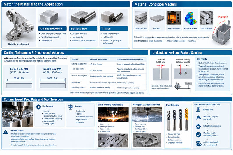
For a robotic arm bracket, aluminum 6061-T6 can provide a useful balance of weight, machinability, and strength. For components exposed to corrosive environments, stainless steel or an appropriate corrosion-resistant alloy may be more suitable. Titanium is often selected when weight and strength are critical, but its higher raw-material and machining costs should be justified by performance requirements.
Material condition matters as well. Plate thickness, flatness, heat treatment, residual stress, and stock quality can affect the finished dimensions. When a component has thin walls or large pockets, removing substantial material from one side can release internal stresses and cause warping. A planned rough-machining, stress-relief where appropriate, and finishing sequence can help control this risk.
Cutting Tolerances, Dimensional Accuracy, and Kerf Compensation
A tolerance defines the permissible variation from a specified dimension. Precision metal cutting should therefore be evaluated against the actual drawing requirements rather than a general claim that a machine is accurate.
For example, a dimension of 50.00 ± 0.10 mm permits a finished size between 49.90 and 50.10 mm. A tighter specification of 50.00 ± 0.02 mm permits only 49.98–50.02 mm. The tighter requirement can increase inspection time, process-control demands, and manufacturing cost.
| Feature | Example requirement | Suitable manufacturing approach |
|---|---|---|
| External sheet profile | ±0.10–0.25 mm | Laser or waterjet, subject to validation |
| Thick plate profile | ±0.10–0.30 mm | Waterjet or suitable cutting process with compensation |
| Precision mounting bore | Drawing-specific close tolerance | CNC boring, reaming, or grinding as appropriate |
| Bearing seat | Close diameter and surface requirements | CNC turning or grinding |
| Flat mating surface | Flatness defined on drawing | CNC milling or surface grinding |
These values are planning examples rather than universal process guarantees. Actual capability must be confirmed with the supplier and the part drawing.
Understand Kerf and Feature Spacing
Kerf is the width of material removed by the cutting process. CAM software compensates for the kerf by offsetting the toolpath, but very small holes, narrow slots, and closely spaced contours may still be limited by the process.
Suppose a laser produces a kerf of 0.20 mm. The cutting path must account for the material removed on either side of the programmed contour to achieve the intended finished dimension. The same principle applies to waterjet cutting, although its wider kerf and possible taper introduce different constraints.
For precision assemblies, designers should specify critical dimensions, datum references, positional tolerances, and mating requirements clearly. If a hole must align with a corresponding component, the hole’s position relative to the datum may matter more than its diameter alone.
Cutting Speed, Feed Rate, and Tool Selection
Cutting speed and feed rate influence productivity, tool life, dimensional accuracy, and edge condition. Increasing speed does not always reduce the total cost because aggressive parameters can create defects, increase tool wear, or require additional finishing.
In CNC milling, cutting speed describes the relative velocity between the cutting edge and the workpiece, while feed rate describes how quickly the tool advances. The correct values depend on the material, cutter diameter, number of cutting edges, tool substrate, coating, machine rigidity, and cutting depth.
For example, machining stainless steel with an unsuitable feed rate can cause excessive heat, work hardening, or rapid tool wear. In contrast, an unstable setup when milling aluminum can lead to chatter, poor surface finish, and dimensional variation. Toolpath strategy, chip evacuation, and coolant selection must be considered together rather than adjusting one parameter in isolation.
Laser and waterjet cutting have their own parameter sets. Laser power, assist-gas pressure, focal position, and travel speed affect edge quality. Waterjet pressure, abrasive flow, nozzle condition, and traverse speed influence cut accuracy and surface striations.
For production work, the best settings are those that maintain a stable, repeatable process at an economically sensible cycle time. Test cuts and first-article inspection help establish suitable parameters before a large batch is released.
Burr Formation, Edge Quality, and Surface Finish
A part can meet its nominal outline and still be unsuitable for assembly if the cut edges contain burrs, dross, sharp corners, or excessive roughness. Edge quality is therefore a functional requirement, not simply an appearance issue.
Laser cutting can leave dross on the lower edge, particularly when material thickness, focus, or gas settings are not optimized. Waterjet cutting may leave visible striations, especially at higher traverse speeds. Mechanical sawing, drilling, and milling can produce burrs that interfere with locating surfaces or damage adjacent components during assembly.
Select Deburring and Finishing According to Function
Common secondary operations include manual deburring, abrasive brushing, tumbling, grinding, and precision edge finishing. The appropriate method depends on the part’s geometry and inspection requirements. Aggressive deburring can unintentionally change a small hole diameter, remove a sharp locating edge, or round a feature that should remain square.
Surface roughness is often expressed as Ra in micrometers. A lower Ra generally indicates a smoother measured surface, but the required value should be specified only when it affects sealing, sliding, fatigue performance, appearance, or another functional requirement.
For example, a non-contacting sheet-metal cover may need only clean, safe edges, whereas a sealing face may require subsequent CNC machining and a defined surface finish. Before anodizing, plating, passivation, or painting, confirm whether the cutting edge needs cleaning or further preparation.
Thermal Distortion and Heat-Affected Zones
Thermal distortion occurs when uneven heating and cooling cause a component to expand, contract, or change shape. A heat-affected zone (HAZ) is the region near a thermally cut edge where heat changes the material’s microstructure or properties without necessarily melting it.
Laser and plasma cutting can create a HAZ, with its extent depending on the material, thickness, heat input, and cutting conditions. Thin sheets with long narrow profiles are particularly vulnerable to movement during cutting. Closely spaced contours may also accumulate heat, affecting dimensional consistency.
Abrasive waterjet cutting avoids a thermal HAZ because it removes material mechanically through the high-velocity abrasive stream. This makes it attractive for parts where heat-related property changes are unacceptable. However, waterjet cutting does not automatically eliminate all dimensional errors; taper, jet lag, and material movement still require control.
To reduce distortion, manufacturers can optimize the cutting sequence, use suitable support and clamping, distribute heat through the nesting strategy, and leave finishing allowance where necessary. For a precision aluminum plate, cutting the blank first and machining critical faces after the part has stabilized may produce a more reliable result than expecting the thermal-cut edge to meet every final specification.
Precision Metal Cutting Costs and Production Efficiency
The cost of precision metal cutting depends on more than the machine’s hourly rate. Material price, cutting time, setup, programming, tool consumption, scrap, inspection, secondary machining, and finishing all contribute to the delivered part cost.
| Cost factor | How it affects the quotation | Practical cost-control measure |
|---|---|---|
| Material grade | Specialty alloys can be significantly more expensive | Choose a suitable grade without unnecessary over-specification |
| Part thickness | Influences cutting speed and equipment requirements | Select thickness based on structural and functional needs |
| Geometry | Small features and complex contours increase cycle time | Simplify non-functional details where possible |
| Tolerances | Tight requirements may need finishing and extra inspection | Apply close tolerances only to critical features |
| Batch quantity | Setup costs are spread differently across order sizes | Plan realistic production quantities |
| Post-processing | Deburring, machining, and coating add cost | Define edge and finish requirements early |
Example: Choosing a Cost-Effective Manufacturing Route
Consider an order for 100 aluminum mounting plates with a complex outer profile and four precision mounting holes. Laser cutting may be an efficient way to produce the blanks, but the holes may need CNC drilling or reaming if their size and position requirements exceed the validated cutting capability.
Producing every feature by milling from solid stock could create unnecessary material waste and machining time. Conversely, relying exclusively on laser cutting could lead to rejected parts if the mounting holes cannot consistently meet the drawing. A combined process may therefore offer the best balance of quality and cost.
To compare supplier quotations fairly, check whether they include material certification when required, dimensional inspection, deburring, surface treatment, packaging, and the specified delivery quantity. The lowest initial price is not necessarily the lowest total cost if the parts require rework or fail during assembly.
Quality Inspection, Applications, and Supplier Selection
Precision metal cutting supports industries that depend on repeatable component geometry, including aerospace, automotive, robotics, medical equipment, electronics, and industrial machinery. Each application places different demands on material traceability, dimensional accuracy, edge condition, and inspection documentation.
Inspection methods should match the feature being verified. Calipers and micrometers are useful for many linear dimensions; pin gauges can check hole sizes; coordinate measuring machines (CMMs) can verify complex geometry and positional relationships. Surface roughness testers, optical measurement systems, and flatness inspection methods may be needed for more demanding parts.
A supplier should review the drawing before production and identify critical-to-function dimensions, datums, material specifications, finishing requirements, and inspection expectations. First-article inspection is particularly valuable when a component has complex geometry or tight tolerances. During repeat production, documented process settings and consistent inspection procedures help detect drift before it creates a large quantity of nonconforming parts.
What to Confirm Before Placing an Order
- Whether the supplier has the appropriate cutting and secondary-machining capabilities.
- Whether the requested tolerance is achievable for the selected material and thickness.
- How burrs, cut-edge taper, surface roughness, and thermal distortion will be controlled.
- Whether inspection reports and material documentation are available when required.
- Whether the quoted lead time includes finishing, inspection, and packaging.
A capable manufacturing partner should explain process limitations clearly and recommend practical alternatives when a design is difficult or unnecessarily expensive to produce.
Precision Metal Cutting Services from Xavier
At Xavier, we understand that precision metal cutting is only one part of producing reliable CNC-machined components. The right manufacturing route depends on material selection, geometry, tolerance requirements, production volume, and the intended application.
For customers developing aluminum brackets, stainless steel housings, steel support components, titanium parts, and other custom metal products, a coordinated approach to cutting, CNC milling, turning, drilling, finishing, and dimensional inspection can help reduce unnecessary operations while maintaining the required part quality.
Rather than applying the same process to every project, Xavier focuses on matching manufacturing methods to the engineering drawing and the component’s functional needs. This helps customers evaluate practical options for prototypes, small batches, and production orders.
Need precision metal cutting or custom CNC-machined parts? Visit CNC Machining Services to discuss your drawings, material requirements, tolerances, and order quantity. Send us your CAD files or technical drawings to request a manufacturing review and quotation for your next project.
As an integrated CNC machining manufacturer and trading supplier, Xavier specializes in custom CNC machining and contract manufacturing of precision metal components. We support CNC machining aluminum, CNC machining PEEK, and CNC machining stainless steel, along with a wide range of other metals, engineering plastics, and custom materials. Our manufacturing capabilities serve diverse industries, including robotics, aerospace, marine engineering, automotive, medical equipment, and precision industrial applications.
As a CNC machining aluminum manufacturer, we provide high-volume CNC machining PEEK services and competitive CNC machining stainless steel pricing. Contact us to discuss your project requirements and receive a tailored quotation.
Some of the images and text in this article are collected and compiled from the internet. If there is anything inappropriate, please contact us for processing.