
Countersink vs Counterbore: How to Choose the Right Hole
10 Key Topics: Countersink vs. Counterbore
- Geometry and fundamental differences between countersink and counterbore holes
- Fastener selection and flush-mounting requirements
- Countersink angles, diameters, and seating accuracy
- Counterbore diameter, depth, and flat-bottom geometry
- CNC machining methods, cutting tools, and process control
- Engineering drawing symbols and dimensioning requirements
- Material thickness, structural strength, and edge distance
- Inspection methods, tolerances, and common machining defects
- Manufacturing costs, production efficiency, and design for manufacturability
- Applications, design examples, and how to choose the right feature
The guide below develops these topics into a practical engineering reference for designers, purchasing engineers, and manufacturers sourcing precision CNC-machined parts. The key principle is to select the hole geometry according to the fastener head, required contact surface, available material thickness, and assembly conditions—not simply the appearance of the finished hole.
1. Geometry and Fundamental Differences Between Countersink and Counterbore
The most important difference between a countersink and a counterbore is the shape of the enlarged section at the entrance of a hole. Although both features allow a fastener head to sit flush with or below the surrounding surface, they create different contact surfaces and are designed for different fastener geometries.
A countersink creates a conical recess with an angled wall. It is commonly used with flat-head screws whose undersides have a matching conical profile. When the screw is tightened correctly, the head seats against the angled surface rather than resting on a flat shoulder.
A counterbore creates a cylindrical recess with parallel walls and a flat bottom. It is commonly used with socket head cap screws, whose cylindrical heads require sufficient diameter clearance and a flat seating surface. The recess can accommodate the screw head below the component’s outer surface.
| Feature | Countersink | Counterbore |
|---|---|---|
| Basic geometry | Conical recess | Cylindrical recess |
| Seating surface | Angled | Flat |
| Typical fastener | Flat-head screw | Socket head cap screw |
| Main dimensions | Hole diameter, included angle, countersink diameter | Hole diameter, recess diameter, recess depth |
| Primary purpose | Match an angled screw head | Accommodate a cylindrical screw head |
| Typical machining tool | Countersink cutter or suitable chamfer tool | Counterbore cutter or CNC end mill |
For example, consider a CNC-machined aluminum mounting plate. If the assembly uses an M6 flat-head screw, a countersink can provide the required angled seating surface. If the same assembly uses an M6 socket head cap screw, a counterbore is generally more appropriate because it provides space for the cylindrical head.
The two features are not interchangeable simply because both can conceal a screw. The fastener specification and intended contact geometry should determine the design.
2. Fastener Selection and Flush-Mounting Requirements
Fastener selection should come before hole design. Engineers need to identify the screw type, head dimensions, installation direction, and required surface clearance before specifying either feature.
Countersinks are useful when the screw head must blend into a flat surface. Typical applications include access panels, sheet-metal assemblies, machine covers, and aerodynamic housings where a protruding fastener could interfere with adjacent components. A correctly matched countersunk screw can sit flush with the surrounding surface or slightly below it, depending on the specified geometry.
Counterbores are more suitable when the design uses a socket head cap screw or another fastener with a cylindrical head and flat bearing surface. They are common in machine fixtures, robotic arm brackets, equipment housings, and structural mounting plates. Recessing the head can also leave clearance for a moving part or protective cover.
Consider a robotic arm bracket made from 6061-T6 aluminum. A socket head cap screw may provide the clamping force needed for the joint, while a counterbore keeps the head from interfering with the robot’s motion envelope. If a flat-head screw is selected instead, the designer must verify that its seating geometry and the reduced material beneath the countersink are suitable for the joint.
Practical selection rule: choose a countersink for a compatible angled fastener head and a counterbore for a compatible flat-bearing cylindrical head. Then check head clearance, installation access, joint loading, and remaining material thickness.
3. Countersink Angles, Diameters, and Seating Accuracy
A countersink’s included angle determines the slope of its conical surface. The correct angle must match the selected fastener standard; choosing a familiar cutter angle without checking the screw specification can result in incomplete contact.
Common countersink angles include 82°, 90°, and 100°. An 82° angle is used for many inch-series flat-head screws, while 90° is common for metric countersunk screws. Some aerospace and specialized fastener systems use 100° designs. These are common examples rather than universal rules, so the actual fastener standard must control the final specification.
The countersink’s major diameter determines how widely the recess opens at the component surface. Its depth depends on the major diameter, the original hole diameter, and the included angle. For an ideal conical recess, the axial depth can be calculated as:
[ h=\frac{D-d}{2\tan(\theta/2)} ]
Where:
- (h) = countersink depth
- (D) = countersink major diameter
- (d) = diameter of the smaller cylindrical hole
- (\theta) = included countersink angle
For example, suppose a hole has a diameter of 5 mm and requires a 10 mm major-diameter countersink with a 90° included angle.
[ h=\frac{10-5}{2\tan45^\circ}=2.5\text{ mm} ]
This is the theoretical conical depth, excluding any additional effects from the cutter tip, edge breaks, and manufacturing tolerances.
An incorrect angle can cause a screw to contact only part of the conical seat. An oversized countersink may allow the screw head to sit too deeply, while an undersized one can leave the head protruding. These problems affect assembly fit and may concentrate contact pressure on an unintended area.
4. Counterbore Diameter, Depth, and Flat-Bottom Geometry
Counterbore design depends primarily on the screw head’s maximum diameter, head height, desired recess, and available material thickness. Unlike a countersink, it does not rely on an included cone angle to establish the seating surface.
The counterbore diameter should provide sufficient clearance for the fastener head without unnecessarily removing material. The depth should accommodate the head to the required height. If the screw must be flush with the surface, the recess depth will generally need to correspond to the head height, subject to the drawing’s tolerances and the actual fastener dimensions. A deeper recess places the head farther below the surface.
Consider an illustrative socket head cap screw with a 10 mm head diameter and a 6 mm head height. A designer might evaluate a counterbore diameter of approximately 10.5–11 mm and a depth around 6–6.3 mm as a starting point. These values are examples only, not a universal M-size specification; the actual screw standard, required clearance, and drawing determine the finished dimensions.
| Design parameter | What to check | Why it matters |
|---|---|---|
| Counterbore diameter | Head diameter plus suitable clearance | Prevents interference during installation |
| Counterbore depth | Head height and required recess | Controls flushness and surface clearance |
| Floor thickness | Remaining material beneath the recess | Helps preserve stiffness and load capacity |
| Hole position | Location relative to datums and mating parts | Prevents assembly misalignment |
| Surface finish | Flatness and seating quality | Supports reliable fastener contact |
A counterbore that is too narrow can prevent installation. One that is too deep can weaken a thin wall or leave insufficient material below the screw head. A rough or uneven floor may also affect seating, particularly when the joint depends on repeatable clamping conditions.
5. CNC Machining Methods, Cutting Tools, and Process Control
Countersinks and counterbores can both be produced using CNC machining, but the tooling strategy and dimensional controls differ.
For a countersink, the machinist may use a dedicated countersink cutter or an appropriate chamfer tool. The tool angle, cutting speed, feed rate, workpiece material, and tool condition influence the resulting surface. Because the cutter engages the workpiece over a changing diameter, chatter and burr formation can affect the finish, especially in thin sheet metal or small holes.
For a counterbore, a dedicated counterbore tool or a CNC end mill can create the larger cylindrical pocket and flat floor. A dedicated tool can be efficient for repeated standard features, while an end mill offers flexibility for custom diameters and depths. Toolpath strategy, workholding rigidity, chip evacuation, and spindle condition all influence dimensional consistency.
Material selection also matters. Aluminum generally machines readily, but thin aluminum sections may deform if the recess removes too much material. Stainless steel can generate more heat and cutting resistance, making tool selection and cutting conditions important. Titanium requires particular attention to heat generation, tool wear, and chip control.
For repeat production, a manufacturer should establish a consistent machining sequence, verify the first part, and monitor tool wear. If anodizing, plating, or another surface treatment follows machining, the drawing and process plan should clarify whether critical dimensions apply before or after finishing.
6. Engineering Drawing Symbols and Dimensioning Requirements
A technically correct design can still be manufactured incorrectly if the drawing does not communicate the required geometry. Avoid relying on phrases such as “recess screw” or “make the head flush” without defining the relevant dimensions and fastener.
For a countersink, the drawing should identify the through or clearance-hole diameter, countersink major diameter or other applicable size definition, included angle, and quantity. The selected fastener standard should be clear whenever it determines the required seat.
For a counterbore, specify the main hole diameter, counterbore diameter, counterbore depth, and quantity. Include tolerances where required, particularly when the feature controls assembly alignment, head clearance, or the remaining wall thickness.
A clear engineering callout should also establish the hole’s location from suitable datums. Where position is critical, geometric dimensioning and tolerancing may be necessary to control the relationship between the hole axis and other features.
A useful drawing review should answer four questions:
- Which fastener will be installed?
- What are the required recess dimensions?
- How should the feature be located relative to mating components?
- Which dimensions or geometric relationships require inspection?
These details reduce interpretation errors during quotation, programming, machining, and final inspection.
7. Material Thickness, Structural Strength, and Edge Distance
The choice between a countersink and a counterbore affects how much material remains around and beneath the fastener. This is especially important for thin-wall housings, lightweight brackets, sheet-metal components, and parts subjected to vibration or repeated loading.
A countersink removes material in a conical shape. As the countersink diameter increases, the recess extends farther into the component. In a thin plate, a deep countersink can leave a narrow section beneath the screw head, reducing the available material for carrying load. Tightening the fastener may then cause local deformation, cracking, or pull-through, depending on the material, geometry, and applied load.
A counterbore removes material in a cylindrical pocket. Its flat floor can provide a suitable bearing surface for a cylindrical screw head, but the pocket also reduces the remaining wall thickness. If the counterbore is too deep, the remaining floor may become insufficiently stiff or strong.
Edge distance is another important factor. A hole positioned too close to the component edge can leave insufficient material between the recess and the outside boundary. Under tightening or service loads, this may increase the risk of edge breakout or cracking.
For example, a 6 mm thick aluminum bracket with a 5 mm deep counterbore leaves only 1 mm of nominal material beneath the recess. Whether this is acceptable depends on the bracket’s load, geometry, alloy, fastener arrangement, and safety requirements. The remaining thickness should never be approved based on a general rule alone.
For aerospace, medical equipment, robotics, and other demanding applications, the design review should consider the fastener preload, material properties, fatigue loading, corrosion exposure, and minimum wall thickness. The correct hole geometry must support both the assembly requirements and the component’s structural function.
8. Inspection Methods, Tolerances, and Common Machining Defects
Inspecting a countersink or counterbore involves more than checking whether a screw fits. The finished geometry must meet the drawing requirements, and the inspection method should be appropriate for each critical dimension.
For countersinks, machinists can use countersink gauges, suitable angle-measuring instruments, optical inspection systems, or coordinate measuring machines (CMMs), depending on the required accuracy and production environment. The major diameter and included angle are particularly important because they determine how the fastener contacts the conical seat.
For counterbores, inspection typically focuses on recess diameter, depth, flatness where specified, and positional accuracy. Depth gauges, bore gauges, height gauges, and CMMs may be appropriate depending on accessibility and tolerance requirements.
| Common defect | Likely cause | Recommended control |
|---|---|---|
| Screw head protrudes | Recess too shallow or incorrect geometry | Verify head dimensions and recess depth |
| Screw head sits too deep | Excessive countersink diameter or recess depth | Check tool offsets and dimensional settings |
| Uneven countersink seating | Incorrect angle, chatter, or poor alignment | Verify cutter angle and machining stability |
| Counterbore floor is rough | Tool wear, poor cutting conditions, or vibration | Optimize toolpath and inspect the cutter |
| Hole location is incorrect | Workholding or coordinate error | Verify datums, fixture position, and CNC offsets |
| Burrs around the opening | Tool condition or unsuitable cutting parameters | Apply controlled deburring and reinspection |
A practical quality-control plan starts with first-article inspection, followed by in-process checks at a frequency appropriate to production risk. For large batches, tool wear and thermal changes should be monitored rather than assuming the first acceptable part guarantees every subsequent part will meet specification.
The specified tolerances should reflect actual assembly needs. A recess that simply provides clearance may not require the same control as one that determines precision seating or alignment. Applying unnecessarily tight tolerances can increase inspection time and machining cost without improving the finished assembly.
9. Manufacturing Costs, Production Efficiency, and Design for Manufacturability
The cost difference between countersinking and counterboring depends on part geometry, material, feature count, required accuracy, tooling, batch size, and inspection requirements. Neither process is automatically cheaper in every application.
Countersinking can be economical when the design uses standard angles and readily available tooling. A simple operation may be completed quickly after drilling, particularly when many identical holes can be machined in one setup. However, demanding seating accuracy or a special angle may require additional tool changes, inspection, and process control.
Counterboring can involve additional material removal and may require careful depth control. A dedicated tool can make repeated standard features efficient, while an end mill can handle nonstandard diameters or complex CNC programs. Deep recesses, small remaining walls, and restricted tool access may increase machining time.
The following comparison illustrates the main cost considerations.
| Cost factor | Countersink | Counterbore |
|---|---|---|
| Typical tooling | Countersink cutter or chamfer tool | Counterbore cutter or end mill |
| Main machining control | Angle and major diameter | Diameter and depth |
| Material removal | Conical recess | Cylindrical pocket |
| Potential cost driver | Tight seating or special angle | Deep recess, larger pocket, or tight depth tolerance |
| Design optimization | Standardize angles and fasteners | Standardize head clearances and pocket sizes |
For example, a component containing 40 standard countersunk holes may be economical to manufacture using a repeatable drilling and countersinking sequence. A fixture plate containing 40 counterbores may also be efficient when the features share a standard diameter and depth. Actual cycle time depends on tool changes, hole spacing, machine access, material, and inspection requirements.
To improve manufacturability, designers should avoid specifying unnecessary recess depth, excessive dimensional precision, and numerous nonstandard fastener sizes. Standard fasteners and repeatable feature dimensions can simplify programming, reduce tool changes, and make inspection more straightforward.
For a CNC machining quotation, providing a complete 2D drawing, 3D CAD model, material specification, surface-finish requirements, quantity, and critical tolerances helps the manufacturer identify cost drivers before production.
10. Applications, Design Examples, and How to Choose the Right Feature
The best way to choose between a countersink and a counterbore is to connect the hole design to the actual assembly requirement. The same component may need both features if it uses different fasteners in different locations.
Practical application examples
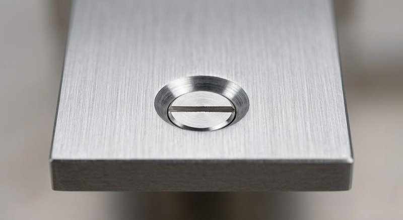
Example A: Flush-mounted aluminum cover
A countersink is appropriate when a compatible flat-head screw must sit flush with the cover. The engineer should verify the included angle, major diameter, surface clearance, and remaining material thickness.
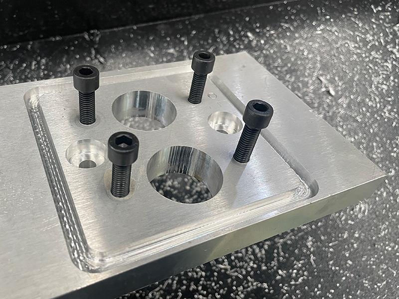
Example B: Precision fixture plate
A counterbore is generally suitable for socket head cap screws that need to sit below the fixture surface. Recess depth and diameter must allow installation without compromising the plate’s rigidity.
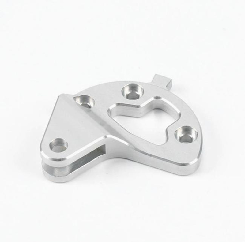
Example C: Robotic arm bracket
The choice depends on the selected fastener and available clearance around moving joints. The design must also account for cyclic loads, vibration, edge distance, and the material remaining around each hole.
A useful selection sequence is:
- Identify the fastener type and its head geometry.
- Determine whether the head requires an angled seat or a flat-bottomed recess.
- Establish the required flushness and clearance.
- Check material thickness, edge distance, and load conditions.
- Define dimensions, tolerances, and inspection requirements.
- Review the feature with the CNC manufacturer before releasing the drawing.
One additional distinction is worth noting: a spotface is not simply another name for a counterbore. A spotface creates a shallow, flat seating area, often on a rough, cast, or uneven surface, without necessarily recessing the entire fastener head. It may be a better choice when the objective is to provide a clean bearing surface rather than hide the fastener.
Final Recommendation: Precision Countersink and Counterbore Machining by Xavier
Choosing between a countersink and a counterbore requires more than matching a hole to a screw. The design must account for fastener geometry, seating accuracy, remaining wall thickness, machining access, dimensional tolerances, and the final assembly’s operating conditions.
At Xavier, we provide CNC machining services for custom metal components, including aluminum, stainless steel, alloy steel, brass, and titanium parts. Our manufacturing approach focuses on translating engineering drawings into practical machining processes while considering dimensional requirements, surface finishing, production efficiency, and assembly fit.
Whether you need countersunk mounting plates, counterbored fixture components, robotic brackets, equipment housings, or other precision-machined parts, clear specifications and early design-for-manufacturability reviews can help reduce avoidable production issues.
Need custom CNC-machined parts with accurate fastener holes? Send your 2D drawings or 3D CAD files to Xavier for a manufacturing review and quotation. Our team can assess your countersink and counterbore requirements, material selection, tolerances, and production needs to help you move from design to finished components.
Explore our CNC machining services to discuss your next project.
As an integrated CNC machining manufacturer and trading company, Xavier specializes in CNC contract manufacturing and precision machining of various metal components. We also offer a range of surface finishing solutions, including CNC zinc electroplating surface finishing, CNC anodizing surface finishing, and CNC chemical conversion coating surface finishing, helping customers meet their functional and appearance requirements.
We are a reliable CNC zinc electroplating manufacturer, providing bulk CNC anodizing services at competitive rates. Contact us to inquire about CNC chemical conversion coating prices and discuss your project requirements.
Some of the images and text in this article are collected and compiled from the internet. If there is anything inappropriate, please contact us for processing.