
How Do You Measure a Surface Finish? A Complete Guide for CNC Machined Parts
10 Key Topics to Understand Before Measuring Surface Finish
- What surface finish means in CNC machining and why it matters.
- How Ra, Rz, Rq, and Rt describe surface roughness.
- Which surface finish measurement tools to use.
- How to measure surface finish with a contact profilometer.
- When to use optical measurement instead of a contact instrument.
- How to use surface roughness comparator samples.
- How to choose measurement direction, cutoff length, and evaluation length.
- How material, machining process, and surface treatment affect results.
- How to interpret surface roughness values and compare them with engineering drawings.
- Common measurement errors and how to improve inspection accuracy.
What Is Surface Finish and Why Does It Matter in CNC Machining?
Surface finish describes the texture and condition of a manufactured surface. In CNC machining, it is influenced by tool geometry, cutting parameters, material properties, machine vibration, coolant conditions, and finishing operations. Although a component may meet its dimensional tolerances, its surface can still fail functional requirements if it is too rough, contains deep scratches, or has inconsistent machining marks.
Surface finish is particularly important for sealing faces, bearing journals, sliding components, hydraulic parts, and precision assemblies. For example, a machined aluminum housing with a sealing face that is too rough may allow fluid to leak, even when the hole diameter and flatness meet their specified tolerances. A shaft with excessive surface roughness may also accelerate wear when it rotates against a bearing or seal.
In manufacturing inspection, surface finish is commonly evaluated through surface roughness parameters such as Ra and Rz. These values provide measurable criteria instead of relying entirely on visual appearance or touch.
Understand Ra, Rz, Rq, and Rt Before Taking Measurements
Before measuring a component, identify the roughness parameter specified on its engineering drawing. Different parameters describe different characteristics of the surface, so a result that passes one requirement may not necessarily satisfy another.
Common surface roughness parameters used in CNC inspection.
| Parameter | What it measures | Typical application |
|---|---|---|
| Ra | Arithmetic average of absolute profile deviations from the mean line | General surface finish acceptance |
| Rz | Mean peak-to-valley height according to the applicable standard | Evaluating prominent peaks and valleys |
| Rq | Root mean square of profile height deviations | Analyzing variations that give greater weight to larger deviations |
| Rt | Total profile height from the highest peak to the deepest valley over the evaluation length | Identifying significant surface extremes |
Ra is the most widely used parameter for general surface roughness control. However, because it averages deviations, a localized deep scratch may have little effect on the final Ra value. Rz and Rt can provide additional information when extreme surface features are important.
For example, two CNC-milled aluminum components might both measure Ra 1.6 µm, but one could contain a deep tool mark while the other has a relatively uniform texture. Their average roughness values may be similar even though their functional quality differs.
Important: Rz definitions can vary between standards and legacy conventions. Always use the parameter definition and measurement standard required by the customer’s drawing rather than assuming that every instrument calculates Rz identically.
Choose the Right Surface Finish Measurement Tool
The appropriate measuring instrument depends on the required accuracy, surface geometry, material, accessibility, and inspection budget. A handheld profilometer is often suitable for routine production checks, while optical instruments are useful for delicate surfaces or more comprehensive topographical analysis.
| Measurement tool | Working principle | Main advantage | Main limitation |
|---|---|---|---|
| Contact profilometer | A stylus traces a surface profile | Quantitative, repeatable measurements | Stylus access and contact may be unsuitable for some surfaces |
| Optical profilometer | Light-based sensing captures surface height information | Non-contact measurement and potential area analysis | Reflectivity, transparency, slope, and instrument settings can affect results |
| Surface roughness comparator | The part is visually or tactually compared with reference samples | Fast shop-floor screening | Subjective and generally unsuitable for precise numerical acceptance |
| Confocal or optical microscope | Optical imaging and height reconstruction characterize surface features | Detailed local analysis | Requires suitable setup and may involve higher equipment costs |
For ordinary turned or milled metal components, a calibrated contact profilometer is usually a practical starting point. For delicate coatings, very small features, or surfaces that could be damaged by stylus contact, a suitable optical system may be preferable.
A comparator is useful for quickly identifying whether a machined surface appears broadly consistent with a known finish, but it should not replace instrument-based verification when a drawing specifies a numerical roughness limit.
How to Measure Surface Finish Using a Contact Profilometer
A contact profilometer, also called a surface roughness tester, measures surface texture by moving a fine stylus across the workpiece. The stylus follows small peaks and valleys, and the instrument converts its vertical movement into a surface profile. Software then calculates the selected parameters, such as Ra, Rz, or Rt.
For CNC-machined metal parts, this method is widely used because it provides numerical results that can be compared with engineering specifications.
Step 1: Prepare the workpiece
Clean the measurement area to remove chips, dust, oil, and loose abrasive particles. Contamination can alter the stylus path and produce readings that do not represent the actual machined surface. If a component has a thin coating or delicate finish, use a cleaning method compatible with that surface.
Secure the workpiece on a stable, vibration-free surface. For small components, use a suitable fixture to prevent movement during measurement.
Step 2: Set the measurement parameters
Select the required roughness parameter, cutoff or filter settings, evaluation length, and measurement range. These settings should follow the applicable drawing and measurement standard.
Step 3: Position the stylus and take a reading
Place the stylus on a suitable, representative area. Ensure that the instrument is aligned correctly and has enough unobstructed travel to complete the measurement. Start the scan without moving the workpiece or disturbing the instrument.
Step 4: Review and repeat the measurement
Record the result and repeat the measurement at additional representative locations when required by the inspection plan. If the readings vary substantially, investigate whether the difference comes from local scratches, tool wear, vibration, inconsistent machining, or an unsuitable measurement setup.

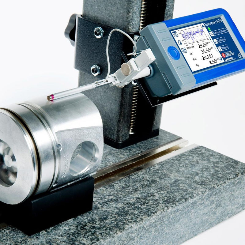
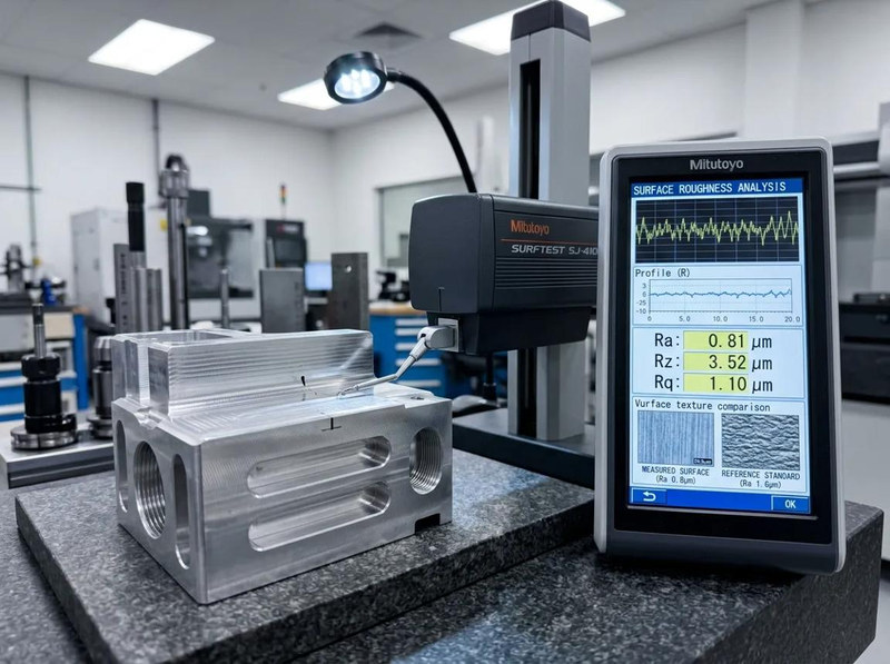
Practical example: Suppose a drawing specifies a maximum Ra of 1.6 µm on a machined steel sealing face. The inspector sets up a suitable calibrated profilometer and obtains readings of 1.2 µm, 1.4 µm, and 1.5 µm at three specified locations. These readings are below the stated limit, provided the drawing’s measurement conditions and acceptance rules are satisfied. The inspector should not automatically average the results to conceal a location that exceeds the permitted limit.
When Should You Use Optical Surface Finish Measurement?
Contact measurement is not ideal for every CNC component. A diamond stylus physically touches the surface, and its tip radius limits how accurately it can enter narrow valleys or resolve very fine features. Contact measurement may also be unsuitable for fragile coatings, soft materials, or certain microstructured surfaces.
Optical measurement systems use light to capture surface information without requiring a stylus to travel across the component. Depending on the instrument, they can measure a profile along a line or reconstruct a three-dimensional surface over an area.
For example, consider a precision-machined component with a reflective polished surface and tiny functional grooves. A suitable optical profilometer may reveal differences in groove depth and surface texture across an area that a single stylus trace would not fully represent.
However, optical instruments are not universally superior. Highly reflective metals, transparent plastics, steep sidewalls, and complex surface geometries can affect measurement performance. The instrument’s optical principle, calibration, resolution, and software settings must be appropriate for the material and feature being inspected.
For routine acceptance of conventional machined surfaces, a contact profilometer may remain the more straightforward choice. For delicate features, complex textures, and three-dimensional surface analysis, an optical system may provide additional information.
How to Use a Surface Roughness Comparator
A surface roughness comparator is a set of reference samples manufactured to represent different surface textures or machining processes. Common examples include turned, milled, ground, and shot-blasted finishes.
To use one, identify the reference series corresponding to the process or texture being evaluated. Compare the sample against the workpiece under consistent lighting and viewing conditions. If the reference samples are designed for tactile comparison, use the manufacturer’s recommended procedure.
For instance, an inspector checking a batch of CNC-turned stainless steel shafts can compare the machined surfaces with suitable turned-finish references. This allows rapid screening for obvious differences between production batches.
However, comparator samples have limitations. Human perception varies, and two surfaces that look or feel similar may have different numerical Ra values. Surface color, reflectivity, machining direction, and local defects can also affect the comparison.
Use a comparator for preliminary checks, operator training, and quick process monitoring. When a customer requires a specific roughness value, verify compliance using an appropriate calibrated instrument.
Set the Correct Measurement Direction, Cutoff, and Evaluation Length
Measurement technique is just as important as the instrument itself. An otherwise accurate profilometer can produce misleading results if the stylus travels in the wrong direction or uses unsuitable filtering and sampling settings.
Measure across the machining lay
The lay is the predominant direction of the surface pattern created by machining. On a conventionally turned shaft, the tool marks often form circumferential patterns. On a milled surface, the pattern depends on the cutter path and tool engagement.
Where practical, the stylus should travel perpendicular to the dominant machining lay when the goal is to evaluate roughness across those marks. Measuring parallel to the marks may produce a different result because the stylus encounters a different surface profile.
Understand cutoff and evaluation length
The cutoff setting separates roughness from longer-wavelength surface variations, while the evaluation length determines the portion of the filtered profile used to calculate the parameter. Incorrect settings can cause readings to differ even when the same part is measured twice.
The following values illustrate commonly encountered legacy ISO 4288-style measurement settings. They are examples, not universal settings for every surface or every current standard.
| Illustrative Ra range | Common cutoff length | Common evaluation length |
|---|---|---|
| 0.1–2.0 µm | 0.8 mm | 4.0 mm |
| 2.0–10.0 µm | 2.5 mm | 12.5 mm |
| 10.0–80.0 µm | 8.0 mm | 40.0 mm |
The required setting depends on the applicable standard, surface profile, parameter, and drawing. The selected evaluation length must also fit the available surface without including unsuitable edges or transitions.
For example, measuring near a shoulder on a turned shaft may capture the geometric transition instead of only the intended cylindrical surface. If the drawing specifies a roughness limit for the shaft diameter, position the measurement within the appropriate functional area and follow the prescribed inspection method.
How Material, Machining Process, and Surface Treatment Affect Measurements
Surface roughness depends on more than the CNC machine’s nominal accuracy. Material hardness, microstructure, cutting-tool condition, feed rate, cutting speed, vibration, and the final finishing operation can all change the measured profile.
For example, aluminum alloys are generally machinable, but built-up edge on a cutting tool can leave rough patches or smeared material. Stainless steel may develop burrs or surface tearing if tool geometry and cutting conditions are unsuitable. Titanium alloys require careful control of cutting heat and tool wear, particularly when a consistent finish is required across a production batch.
Different processes also produce different surface characteristics.
| Manufacturing process | Illustrative Ra range | Typical considerations |
|---|---|---|
| CNC milling or turning | 0.8–3.2 µm | Tool marks, feed marks, vibration |
| Grinding | 0.1–0.8 µm | Wheel condition, dressing, burn marks |
| Lapping or fine polishing | 0.025–0.1 µm | Flatness, scratches, process consistency |
| Sandblasting | Highly process-dependent | Impact texture, media size, surface uniformity |
These are indicative examples, not guaranteed process capabilities. Actual results depend on material, equipment, geometry, and inspection conditions.
Surface treatment introduces another consideration. Anodizing, electroless nickel plating, and other coatings can change the surface profile or affect how the surface is measured. The final result may depend on coating thickness, pretreatment, deposition characteristics, and the original machined texture.
If a customer specifies a finish requirement after coating, inspect the component in its required final condition. Measuring the uncoated part alone does not establish that the finished component meets the same requirement.
For Xavier’s CNC manufacturing projects, this distinction matters when deciding whether a surface finish requirement applies before or after a secondary finishing operation.
How to Interpret Surface Roughness Values on Engineering Drawings
A surface roughness value must be interpreted in the context of its units, parameter, limit, and associated specification. A note such as Ra 1.6 µm identifies a roughness parameter and target value, but the drawing or applicable standard must establish the acceptance criteria and measurement conditions.
Surface roughness is commonly expressed in micrometers (µm) or microinches (µin). The conversion is:
[ 1\ \mu m \approx 39.37\ \mu in ]
| Ra in micrometers | Approximate Ra in microinches | General interpretation |
|---|---|---|
| 3.2 µm | 126 µin | Relatively coarse machined finish |
| 1.6 µm | 63 µin | Finer general machined finish |
| 0.8 µm | 31.5 µin | Fine machined or ground finish |
| 0.4 µm | 15.7 µin | Finer finish, often requiring additional process control |
| 0.1 µm | 3.94 µin | Very fine finish, often associated with precision finishing |
These descriptions are indicative rather than formal classifications. A suitable finish depends on what the part must do.
Example: a hydraulic sealing component. A supplier receives a drawing specifying Ra 0.8 µm on a sealing face. The surface must meet the specified roughness requirement, but the inspector should also consider flatness, scratches, burrs, and other drawing requirements. Passing Ra alone does not guarantee leak-tight performance.
When reviewing a drawing, confirm the following:
- The specified parameter, such as Ra or Rz.
- The required units and any maximum or minimum limit.
- The applicable surface texture standard.
- Whether the requirement applies before or after coating.
- The measurement locations and acceptance procedure.
- Any additional restrictions on scratches, waviness, or isolated defects.
If the drawing does not define sufficient measurement information, clarify the requirement with the customer before production inspection. This prevents unnecessary disputes caused by different instruments or inconsistent measurement settings.
Common Surface Finish Measurement Errors and How to Avoid Them
Even a high-quality instrument cannot compensate for poor inspection practice. Several common errors can lead to inconsistent results between a CNC supplier and its customer.
| Common error | Why it causes problems | Recommended corrective action |
|---|---|---|
| Measuring a dirty surface | Debris or oil can interfere with the stylus or optical signal | Clean the surface using a compatible method |
| Measuring parallel to machining marks | The measured profile may not represent the dominant surface texture | Select the direction required by the inspection method |
| Using the wrong cutoff | Roughness and waviness may be separated incorrectly | Match the applicable standard and drawing |
| Measuring near an edge | Geometry changes can distort the profile | Choose a suitable measurement location |
| Ignoring calibration | Instrument bias can affect acceptance decisions | Verify calibration and check against a suitable reference |
| Taking only one reading | Local scratches or process variation may go undetected | Follow the inspection plan for measurement locations and repeats |
| Relying on Ra alone | Isolated deep scratches may be hidden by averaging | Add Rz, Rt, visual inspection, or other checks where appropriate |
Consider a production batch of 100 precision-machined steel components. If the first part passes inspection but the cutting tool gradually wears, later parts may develop different surface characteristics. A structured sampling plan helps identify this change before it causes a larger batch of nonconforming parts.
When results disagree between two facilities, repeat the measurements using the same parameter, units, measurement direction, cutoff, evaluation length, and acceptance criteria. Check instrument calibration and measurement location before concluding that either party’s equipment is defective.
The objective is not simply to obtain a low roughness number. It is to produce a reliable measurement that reflects the component’s actual surface condition and functional requirements.
Choose Xavier for CNC Machining with Controlled Surface Finish
At Xavier, surface finish is an important consideration when manufacturing precision metal components for international B2B customers. The appropriate machining process and inspection method depend on the material, component geometry, drawing requirements, production quantity, and intended application.
Whether your project involves CNC-milled aluminum brackets, turned stainless steel shafts, precision steel components, or parts requiring secondary surface treatments, clearly defined inspection requirements help align manufacturing and quality control from the beginning.
When requesting a quotation, provide your 2D engineering drawing or 3D CAD model, material specification, required surface roughness values, coating requirements, and critical inspection dimensions. This allows the manufacturing team to assess process feasibility and identify any special measurement requirements before production begins.
Need precision CNC machined parts with specified surface finish requirements? Contact Xavier to discuss your drawings, manufacturing requirements, and inspection expectations. Our team can help evaluate a suitable machining and finishing approach for your project.
As an integrated CNC machining manufacturer and trading supplier, Xavier specializes in CNC contract manufacturing and the precision machining of various metal components. We offer a range of surface treatment solutions, including CNC electroless nickel plating surface finishing, CNC passivation surface finishing, and CNC chemical conversion coating surface finishing to help meet different manufacturing and component protection requirements.
As a CNC electroless nickel plating surface finishing manufacturer, we provide bulk CNC passivation surface finishing services and offer competitive CNC chemical conversion coating surface finishing prices. Contact us to discuss your project specifications and request a quotation.
Some of the images and text in this article are collected and compiled from the internet. If there is anything inappropriate, please contact us for processing.