
Rapid Prototyping and Manufacturing: Accelerating Product Development from Concept to Production
In today’s highly competitive manufacturing landscape, companies are expected to transform innovative ideas into market-ready products faster than ever before. Whether developing consumer electronics, automotive components, aerospace assemblies, or medical devices, reducing product development cycles has become a critical competitive advantage.
Rapid prototyping and manufacturing combine advanced digital design tools with modern production technologies to shorten the journey from concept to finished product. Instead of spending months producing molds or waiting for traditional manufacturing processes, engineers can now validate designs, test functionality, optimize manufacturability, and begin low-volume production within days.
Modern rapid manufacturing no longer relies on a single technology. CNC machining, industrial 3D printing, vacuum casting, sheet metal fabrication, injection molding, and hybrid manufacturing workflows all play different roles depending on project requirements. Selecting the right process at each development stage directly impacts cost, lead time, product quality, and scalability.
This guide explains how rapid prototyping integrates into modern manufacturing, the technologies available, material selection strategies, and how businesses can efficiently transition from prototype to production.
What Is Rapid Prototyping and How Does It Fit into Modern Manufacturing?
Rapid prototyping refers to the fast fabrication of physical parts directly from CAD models using digital manufacturing technologies. Unlike conventional manufacturing, which often requires expensive tooling before production begins, rapid prototyping allows engineers to evaluate a design with minimal upfront investment.
Today’s manufacturers use rapid prototyping not only for appearance models but also for engineering validation, assembly testing, customer demonstrations, regulatory approval, and pilot production.
Rather than replacing traditional manufacturing, rapid prototyping complements it by reducing engineering uncertainty before mass production begins.
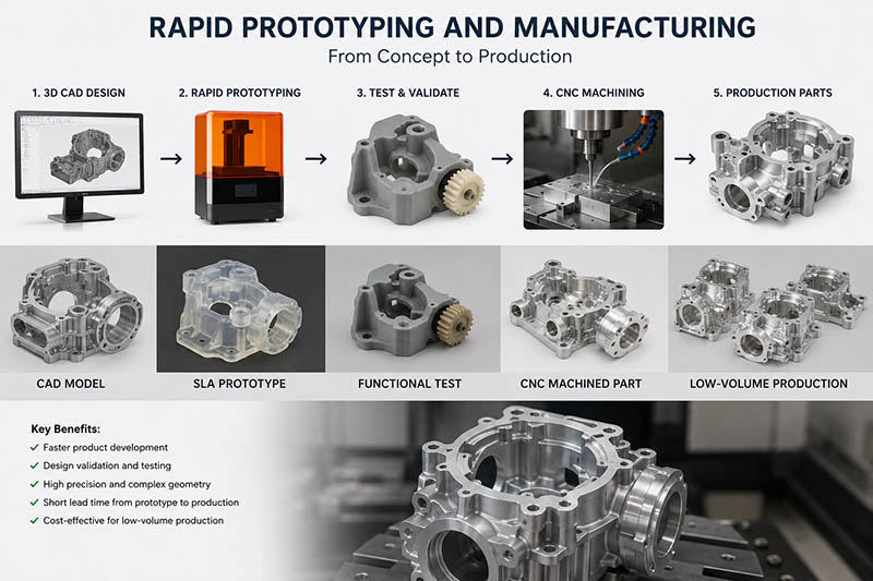
The Evolution of Product Development
Traditional product development followed a relatively slow sequence:
| Traditional Workflow | Typical Duration |
|---|---|
| Product Design | 2-4 weeks |
| Tool Design | 3-8 weeks |
| Mold Manufacturing | 4-10 weeks |
| Sample Production | 2-3 weeks |
| Engineering Modification | Repeat tooling |
A single design modification often required rebuilding molds or fixtures, increasing both development costs and project timelines.
Modern rapid manufacturing dramatically changes this workflow.
| Modern Digital Workflow | Typical Duration |
|---|---|
| CAD Design | Days |
| Prototype Manufacturing | 1-7 Days |
| Engineering Validation | Days |
| Design Optimization | Hours |
| Functional Prototype | Days |
| Pilot Production | 1-2 Weeks |
Digital manufacturing significantly reduces iteration cycles because engineers can immediately update CAD files without redesigning production tooling.
Why Rapid Prototyping Matters
Nearly every new product experiences multiple engineering revisions before production.
Typical reasons include:
- Components interfere during assembly
- Weight exceeds design targets
- Structural rigidity is insufficient
- Surface finish fails customer expectations
- Manufacturing costs exceed budget
- Material properties require improvement
Without rapid prototyping, each design revision introduces substantial delays.
Rapid prototyping enables engineers to detect problems before committing to expensive production investments.
For example, an aluminum electronics enclosure may initially appear perfect in CAD software. However, once machined, engineers might discover:
- Screw holes are difficult to access.
- Cable routing interferes with connectors.
- Internal ribs reduce machining efficiency.
- Heat dissipation is lower than expected.
Correcting these issues during prototype development may cost hundreds of dollars.
Correcting them after injection mold production may cost tens of thousands.
Key Objectives of Rapid Prototyping
Rapid prototyping serves multiple engineering objectives throughout product development.
| Objective | Benefit |
|---|---|
| Design Verification | Confirm geometry accuracy |
| Functional Testing | Evaluate real-world performance |
| Assembly Validation | Ensure parts fit correctly |
| Customer Approval | Demonstrate realistic products |
| Manufacturing Evaluation | Improve production feasibility |
| Material Testing | Compare multiple material options |
Different prototype stages often prioritize different objectives.
Early prototypes may focus on appearance.
Engineering prototypes emphasize functionality.
Pilot production validates manufacturing repeatability.
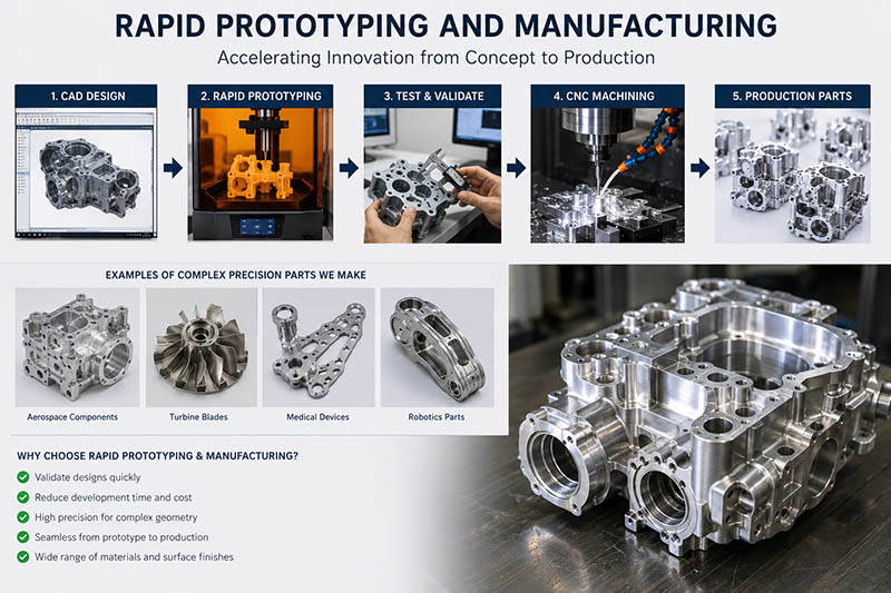
Digital Manufacturing Enables Faster Decisions
Modern manufacturing relies heavily on digital engineering.
Instead of manually interpreting drawings, manufacturers work directly from:
- STEP files
- IGES files
- SolidWorks models
- CATIA assemblies
- Siemens NX models
- Creo designs
These digital files integrate seamlessly with:
- CNC machining centers
- Industrial 3D printers
- Coordinate Measuring Machines (CMM)
- CAM programming software
- Simulation software
The result is an uninterrupted digital workflow from concept through inspection.
Prototype Accuracy Has Improved Significantly
One common misconception is that prototypes are merely rough models.
Modern rapid manufacturing produces engineering-grade components capable of meeting production-level tolerances.
Typical machining capabilities include:
| Feature | Typical Accuracy |
|---|---|
| CNC Milling | ±0.01 mm |
| CNC Turning | ±0.005 mm |
| Surface Grinding | ±0.002 mm |
| 3D Printing (Industrial SLA) | ±0.05-0.15 mm |
| Vacuum Casting | ±0.15-0.30 mm |
These tolerances allow engineers to perform realistic mechanical testing before production begins.
Design Iteration Is the Biggest Advantage
Rapid prototyping encourages continuous product improvement.
Consider an automotive aluminum bracket.
Version 1 weighs 850 grams.
Engineers remove unnecessary material using topology optimization.
Version 2 weighs 720 grams.
Further CNC optimization reduces machining operations.
Version 3 weighs 660 grams while maintaining identical strength.
Instead of redesigning expensive tooling after every modification, manufacturers simply produce another prototype within a few days.
This iterative workflow improves:
- Product quality
- Manufacturing efficiency
- Cost optimization
- Structural performance
- Customer satisfaction
Rapid Prototyping Across Different Development Stages
Rapid prototyping supports every phase of product development.
| Development Stage | Prototype Purpose |
|---|---|
| Concept Validation | Visual appearance |
| Engineering Design | Mechanical testing |
| Functional Testing | Performance verification |
| Customer Evaluation | Marketing samples |
| Certification | Regulatory testing |
| Pilot Production | Manufacturing validation |
As products mature, prototype requirements gradually shift from appearance toward manufacturability.
Example: Developing a Precision Aerospace Component
Imagine an aerospace company developing a lightweight titanium mounting bracket.
The engineering team begins with CAD modeling before producing the first CNC-machined prototype.
During testing, finite element analysis predicted sufficient strength, but physical load testing revealed localized stress concentrations near two mounting holes.
The design team increased the fillet radius, adjusted the wall thickness, and optimized pocket geometry.
A second prototype reduced peak stress by nearly 18% while lowering overall weight by approximately 9%.
The updated component then underwent vibration testing, thermal cycling, and assembly validation before moving into a pilot production run of 100 units.
Without rapid prototyping, identifying these issues after production tooling had been completed could have resulted in months of engineering delays and substantial redesign costs.
This example demonstrates why rapid prototyping is not simply about producing parts quickly—it is a structured engineering process that minimizes technical risk, improves product performance, and accelerates time-to-market.
Rapid Prototyping Technologies: CNC Machining vs. 3D Printing vs. Vacuum Casting
Selecting the appropriate rapid prototyping technology is one of the most important decisions during product development. While all three major processes—CNC machining, 3D printing, and vacuum casting—can produce prototype parts quickly, each offers distinct advantages, limitations, and ideal applications.
The best choice depends on several factors, including part geometry, required tolerances, material properties, production quantity, surface finish, mechanical strength, and project budget. Understanding these differences helps engineers avoid unnecessary costs while ensuring prototypes accurately represent the final product.
CNC Machining: High Precision for Functional Prototypes
CNC machining remains one of the most widely used rapid manufacturing methods because it produces parts from production-grade materials with excellent dimensional accuracy. Unlike additive manufacturing, CNC machining removes material from a solid block using computer-controlled cutting tools.
Since the prototype is manufactured from the same material intended for production, engineers can evaluate real mechanical properties such as tensile strength, hardness, thermal conductivity, and wear resistance.
Advantages of CNC Machining
- Excellent dimensional accuracy (typically ±0.01 mm)
- Superior surface finish after machining
- Wide range of metals and engineering plastics
- High structural integrity
- No layer lines or anisotropic strength
- Ideal for functional testing and precision assemblies
Limitations
- Material waste is higher than additive manufacturing.
- Complex internal cavities may require multiple setups or special tooling.
- Extremely intricate organic shapes can increase machining time and cost.
Common Materials
| Metal Materials | Plastic Materials |
|---|---|
| Aluminum 6061 | ABS |
| Aluminum 7075 | POM (Delrin) |
| Stainless Steel 304 | Nylon (PA6) |
| Stainless Steel 316 | PTFE |
| Brass | PEEK |
| Copper | PC |
| Titanium | PMMA |
| Tool Steel | UHMW-PE |
Typical Applications
- Aerospace brackets
- Medical instruments
- Automotive transmission components
- Robotics housings
- Electronic enclosures
- Precision gears
- Hydraulic manifolds
- Heat sinks
For example, an aerospace mounting bracket requiring a tolerance of ±0.01 mm and high fatigue resistance is far better suited to CNC machining than 3D printing. Likewise, a precision aluminum heat sink benefits from the excellent thermal conductivity of machined aluminum, allowing engineers to perform realistic thermal performance tests.
3D Printing: Speed and Design Freedom
3D printing, also known as additive manufacturing, builds parts layer by layer directly from a digital CAD model. This process eliminates the need for cutting tools or molds, making it particularly effective for rapidly producing complex geometries.
Several industrial 3D printing technologies are commonly used in rapid prototyping:
| Technology | Material | Typical Use |
|---|---|---|
| FDM | Thermoplastics | Concept models |
| SLA | Photopolymer Resin | High-detail appearance prototypes |
| SLS | Nylon Powder | Functional engineering parts |
| MJF | Nylon Powder | Production-quality plastic components |
| DMLS/SLM | Metal Powder | Metal functional prototypes |
Advantages
- Exceptional geometric freedom
- Internal channels and lattice structures
- Minimal material waste
- Fast turnaround for complex designs
- No tooling required
- Easy design iteration
Limitations
- Surface finish may require post-processing.
- Mechanical properties vary depending on the printing technology.
- Layer orientation can influence strength.
- Metal printing is relatively expensive for simple geometries.
Ideal Applications
- Ergonomic design studies
- Medical anatomical models
- Fluid flow channels
- Lightweight lattice structures
- Architectural models
- Consumer product concept validation
For instance, a designer developing a handheld power tool can produce multiple ergonomic grip designs overnight using SLA printing. These prototypes allow users to evaluate comfort and usability before any investment is made in production tooling.
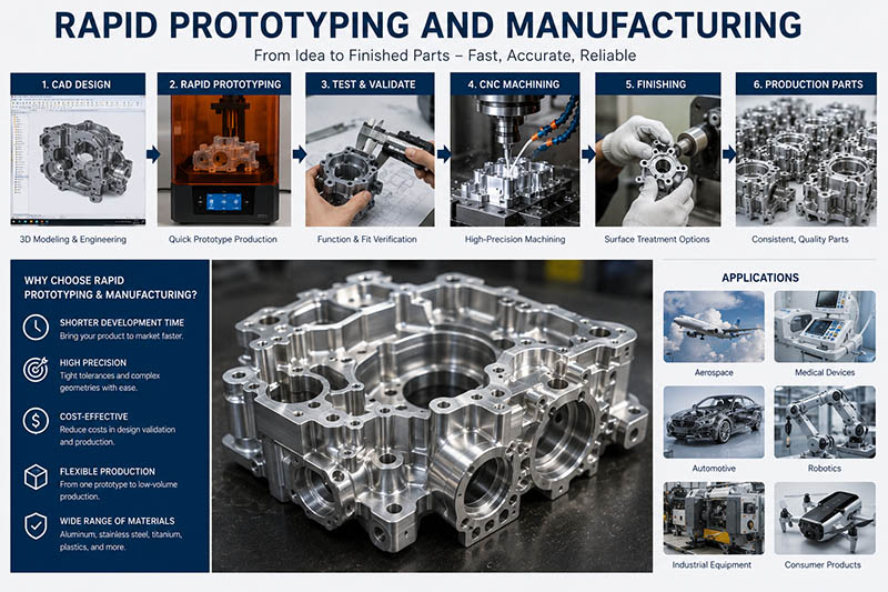
Vacuum Casting: Cost-Effective Small-Batch Production
Vacuum casting bridges the gap between one-off prototypes and full-scale injection molding. The process begins with a master model—often produced by CNC machining or SLA 3D printing—which is used to create a silicone mold. Liquid polyurethane resin is then poured into the mold under vacuum to minimize air bubbles and improve detail reproduction.
A single silicone mold can typically produce 15–25 high-quality parts, making vacuum casting an economical solution for low-volume production.
Advantages
- Excellent surface finish
- Lower cost than injection molding
- Fast production of multiple identical parts
- Wide range of resin properties
- Suitable for colored and transparent components
Limitations
- Silicone molds have a limited lifespan.
- Dimensional accuracy is lower than CNC machining.
- Mechanical properties differ from production thermoplastics.
Typical Applications
- Consumer electronics housings
- Medical device covers
- Automotive interior trims
- Product demonstration samples
- Marketing prototypes
- Functional plastic assemblies
A startup launching a new smart home device, for example, may require 100 demonstration units for trade shows and customer trials. Producing an injection mold at this stage would be prohibitively expensive. Vacuum casting offers an ideal solution by delivering visually appealing, functional parts in a fraction of the time and cost.
Comparison of Major Rapid Prototyping Technologies
The following table summarizes the key differences among CNC machining, 3D printing, and vacuum casting:
| Feature | CNC Machining | 3D Printing | Vacuum Casting |
|---|---|---|---|
| Dimensional Accuracy | Excellent (±0.01 mm) | Good (±0.05–0.15 mm) | Moderate (±0.15–0.30 mm) |
| Surface Finish | Excellent | Moderate (post-processing often required) | Excellent |
| Material Strength | Production-grade | Varies by technology | Good for functional plastics |
| Internal Complex Geometry | Limited | Excellent | Moderate |
| Production Quantity | 1–500+ | 1–50 | 10–200 |
| Tooling Required | No | No | Silicone mold only |
| Lead Time | 2–7 days | 1–5 days | 5–10 days |
| Unit Cost for Single Part | Moderate | Low to Moderate | High |
| Unit Cost for Small Batch | Moderate | Higher | Low |
| Best Use Case | Functional prototypes | Complex concepts | Low-volume production |
How to Choose the Right Process
No single technology is suitable for every project. The selection should be based on engineering priorities rather than convenience.
| Project Requirement | Recommended Process | Reason |
|---|---|---|
| Highest dimensional accuracy | CNC Machining | Precision tolerances and production-grade materials |
| Complex internal channels | 3D Printing | Additive manufacturing enables impossible geometries |
| Functional aluminum prototype | CNC Machining | Real material properties and excellent finish |
| Lightweight lattice structure | 3D Printing | Efficient material usage and design freedom |
| 50–200 plastic demonstration units | Vacuum Casting | Economical for low-volume production |
| Metal parts requiring fatigue testing | CNC Machining | Accurate mechanical performance |
| Transparent product housing | Vacuum Casting | High-quality clear resin options |
| Consumer product appearance model | SLA 3D Printing | Fine detail and smooth surfaces |
Hybrid Manufacturing: Combining Technologies for Better Results
In many real-world projects, manufacturers do not rely on a single process. Instead, they combine multiple technologies to optimize speed, cost, and quality.
Consider the development of a wearable medical device:
- SLA 3D printing is used to create an initial ergonomic prototype for evaluating user comfort.
- CNC machining produces an aluminum internal frame to verify structural integrity and precise fit.
- Vacuum casting manufactures 100 functional plastic housings for clinical trials and customer demonstrations.
- Once the design is finalized, injection molding is introduced for high-volume production.
This hybrid approach allows each manufacturing technology to contribute where it performs best, reducing development risks while shortening the product launch timeline.
Example: Rapid Development of an Industrial Robotics End Effector
A robotics manufacturer needed to develop a custom gripper for an automated assembly line within six weeks.
- Week 1: Engineers created a concept model using FDM 3D printing to verify the overall geometry.
- Week 2: Critical aluminum components were CNC machined to test precision alignment and gripping force.
- Week 3–4: Design refinements were implemented based on performance testing.
- Week 5: Vacuum casting produced 50 polymer covers for customer evaluation and pilot installation.
- Week 6: The validated design transitioned directly into low-volume manufacturing.
By combining multiple rapid manufacturing technologies, the company reduced development time by more than 40% compared with its traditional workflow and identified several assembly issues before committing to production tooling.
Material Selection for Rapid Prototypes and Functional Parts
Selecting the right material is just as important as choosing the manufacturing process. Even with the most advanced CNC machines or industrial 3D printers, an unsuitable material can lead to inaccurate test results, premature failures, unnecessary costs, or delays during product development.
Material selection should always be based on the prototype’s intended purpose. For example, a concept model used for appearance evaluation has very different requirements than a functional prototype designed for mechanical testing or environmental validation.
Experienced engineers typically evaluate multiple factors before selecting a material, including:
- Mechanical strength
- Weight
- Machinability or printability
- Corrosion resistance
- Heat resistance
- Wear resistance
- Electrical conductivity
- Surface finish requirements
- Cost
- Availability
- Production scalability
Rather than selecting the “strongest” material, manufacturers aim to find the best balance between performance, manufacturability, and budget.
Choosing Materials Based on Prototype Objectives
Different development stages require different material properties.
| Prototype Objective | Recommended Material Type | Primary Focus |
|---|---|---|
| Appearance Model | ABS, Resin, PMMA | Visual quality |
| Assembly Verification | Aluminum, POM | Dimensional accuracy |
| Functional Testing | Aluminum, Stainless Steel, PEEK | Mechanical properties |
| Thermal Evaluation | Aluminum, Copper | Heat dissipation |
| Electrical Components | FR4, PEEK, PC | Electrical insulation |
| Wear Testing | Tool Steel, Bronze | Durability |
| Medical Devices | Titanium, PEEK | Biocompatibility |
| Aerospace Components | Titanium, Aluminum 7075 | Lightweight strength |
The closer the prototype material matches the final production material, the more reliable the testing results will be.
Aluminum Alloys: The Most Popular Choice for CNC Prototypes
Aluminum is one of the most frequently used materials in rapid manufacturing because it combines excellent machinability, low weight, good corrosion resistance, and favorable mechanical properties.
Among the many available grades, 6061 and 7075 are the most common.
| Property | Aluminum 6061 | Aluminum 7075 |
|---|---|---|
| Density | 2.70 g/cm³ | 2.81 g/cm³ |
| Tensile Strength | ~310 MPa | ~570 MPa |
| Corrosion Resistance | Excellent | Good |
| Machinability | Excellent | Very Good |
| Weldability | Excellent | Limited |
| Typical Applications | General engineering | Aerospace, robotics |
6061 aluminum is ideal for most prototype applications because it is easy to machine, cost-effective, and offers balanced mechanical performance.
7075 aluminum, often referred to as an aerospace-grade alloy, provides significantly higher strength while maintaining a relatively low weight. It is commonly used for aircraft brackets, racing components, UAV structures, and high-performance robotics.
Example
A robotics company developing an autonomous mobile robot initially selected 6061 aluminum for the chassis. During durability testing, engineers observed excessive deformation under repeated impact loads. By switching to 7075 aluminum, the chassis stiffness increased considerably while the overall weight rose by less than 5%, resulting in a more robust design without compromising mobility.
Stainless Steel: Strength, Corrosion Resistance, and Reliability
Stainless steel is widely used for prototypes that must withstand harsh environments, repeated mechanical loads, or chemical exposure.
The two most common grades are 304 and 316 stainless steel.
| Property | Stainless Steel 304 | Stainless Steel 316 |
|---|---|---|
| Corrosion Resistance | Excellent | Superior |
| Saltwater Resistance | Moderate | Excellent |
| Strength | High | High |
| Machinability | Good | Moderate |
| Cost | Lower | Higher |
304 stainless steel is suitable for food equipment, industrial machinery, and general engineering applications.
316 stainless steel contains molybdenum, significantly improving its resistance to chlorides and marine environments. It is frequently chosen for offshore equipment, medical devices, and chemical processing systems.
Although stainless steel offers excellent durability, it generally requires longer machining times than aluminum, increasing manufacturing costs.
Titanium: High Performance for Critical Applications
Titanium is known for its exceptional strength-to-weight ratio and outstanding corrosion resistance.
Its primary advantages include:
- High fatigue resistance
- Excellent biocompatibility
- Resistance to seawater corrosion
- Low density compared with steel
- High operating temperature capability
Common applications include:
- Aerospace structural components
- Medical implants
- Surgical instruments
- Racing components
- Satellite hardware
However, titanium is more difficult to machine than aluminum due to its lower thermal conductivity and tendency to generate heat during cutting. Manufacturers must use optimized cutting parameters and specialized tooling to maintain dimensional accuracy and tool life.
Engineering Plastics for Functional Prototypes
Not all prototypes require metal. Many engineering applications benefit from high-performance plastics that combine low weight with excellent mechanical and chemical properties.
Some of the most widely used engineering plastics include:
| Material | Key Advantages | Typical Applications |
|---|---|---|
| ABS | Easy machining, low cost | Consumer products |
| POM (Delrin) | Low friction, dimensional stability | Gears, bushings |
| Nylon (PA6/PA12) | Toughness, wear resistance | Bearings, rollers |
| Polycarbonate (PC) | High impact strength | Protective covers |
| PMMA (Acrylic) | Optical clarity | Display panels |
| PTFE | Chemical resistance | Seals, valves |
| PEEK | High temperature, high strength | Aerospace, medical |
| PEI | Flame resistance | Electrical insulation |
Among these materials, PEEK is often considered one of the highest-performing engineering plastics. It can operate continuously at temperatures above 250°C while maintaining excellent mechanical strength and chemical resistance.
For applications where metal weight is undesirable, PEEK is increasingly used as an alternative to aluminum or stainless steel.
Material Selection Based on Industry Requirements
Different industries prioritize different material characteristics.
| Industry | Preferred Materials | Key Requirement |
|---|---|---|
| Aerospace | Aluminum 7075, Titanium | Lightweight, high strength |
| Automotive | Aluminum 6061, Steel, Nylon | Cost-performance balance |
| Medical | Titanium, PEEK, 316 Stainless Steel | Biocompatibility |
| Electronics | Aluminum, PC, ABS | Heat dissipation and insulation |
| Industrial Automation | Aluminum, POM, Tool Steel | Precision and durability |
| Marine | 316 Stainless Steel, Bronze | Corrosion resistance |
Selecting materials according to industry standards helps ensure that prototype testing accurately reflects real-world operating conditions.
Balancing Performance and Cost
Material performance often increases with cost, making optimization essential during product development.
The following comparison illustrates this trade-off:
| Material | Relative Cost | Performance Level | Best Use |
|---|---|---|---|
| ABS | Low | Moderate | Appearance models |
| Aluminum 6061 | Low-Medium | High | General functional prototypes |
| Stainless Steel 304 | Medium | High | Industrial equipment |
| Aluminum 7075 | Medium-High | Very High | Lightweight structural parts |
| Titanium Ti-6Al-4V | High | Excellent | Aerospace and medical |
| PEEK | High | Excellent | High-temperature engineering |
Rather than automatically choosing premium materials, engineers should evaluate whether the additional performance justifies the increased manufacturing cost.
Surface Treatments Can Enhance Material Performance
Material selection does not end once the raw material is chosen. Surface treatments often play a crucial role in improving durability, corrosion resistance, and appearance.
Some common post-processing options include:
| Surface Treatment | Suitable Materials | Primary Benefits |
|---|---|---|
| Anodizing | Aluminum | Improved corrosion resistance, enhanced appearance |
| Hard Anodizing | Aluminum | Increased surface hardness and wear resistance |
| Electropolishing | Stainless Steel | Smoother finish, improved corrosion resistance |
| Passivation | Stainless Steel | Enhanced corrosion protection |
| Zinc Plating | Carbon Steel | Basic corrosion resistance |
| Nickel Plating | Steel, Copper | Wear and corrosion protection |
| Powder Coating | Various Metals | Decorative and protective finish |
For example, an aluminum prototype used in outdoor equipment may perform well during mechanical testing but still require anodizing to withstand long-term exposure to moisture and UV radiation.
Case Study: Selecting the Optimal Material for a UAV Camera Mount
A manufacturer developing a camera mounting bracket for an unmanned aerial vehicle (UAV) evaluated three materials during the prototyping phase: 6061 aluminum, 7075 aluminum, and carbon fiber-reinforced nylon.
The engineering team established the following design goals:
- Keep the total weight below 180 g
- Maintain high rigidity under continuous vibration
- Minimize manufacturing cost for prototype iterations
- Allow easy machining for design modifications
The initial prototype was CNC machined from 6061 aluminum, providing excellent machinability and reducing lead time. However, vibration testing at high flight speeds revealed slight flexing around the mounting arms.
The second prototype used 7075 aluminum, increasing stiffness by approximately 35% while adding only a minimal weight increase. This version successfully passed structural testing but slightly exceeded the target budget.
To explore additional weight savings, engineers produced a third prototype using carbon fiber-reinforced nylon through industrial 3D printing. Although the weight dropped by nearly 20%, long-term fatigue testing showed reduced dimensional stability under continuous vibration.
After comparing all three options, the company selected 7075 aluminum for production because it provided the best combination of strength, precision, and long-term reliability. The development process demonstrated that material selection is rarely based on a single property; instead, it requires balancing performance, manufacturability, weight, cost, and service life.
From Prototype to Low-Volume Manufacturing: Choosing the Right Production Strategy
Creating a successful prototype is only the beginning of the product development journey. The next challenge is determining how to transition from a single validated prototype to low-volume manufacturing while maintaining quality, controlling costs, and preparing for mass production.
Many products fail during this stage—not because the design is flawed, but because the manufacturing strategy is not optimized. A prototype that performs perfectly in the laboratory may become expensive, difficult to manufacture, or inconsistent when scaled to hundreds or thousands of units.
A well-planned production strategy minimizes these risks by gradually increasing production volume while continuously validating quality, manufacturability, and process stability.
Understanding the Different Production Stages
Manufacturing generally progresses through several distinct phases, each with its own objectives and production methods.
| Development Stage | Typical Quantity | Primary Goal | Recommended Process |
|---|---|---|---|
| Concept Prototype | 1–5 parts | Validate appearance and dimensions | 3D Printing, CNC Machining |
| Engineering Prototype | 5–20 parts | Functional and mechanical testing | CNC Machining |
| Pre-Production Prototype | 20–100 parts | Assembly verification | CNC, Vacuum Casting |
| Pilot Production | 100–1,000 parts | Validate manufacturing process | CNC, Soft Tooling |
| Mass Production | 1,000+ parts | Cost-efficient manufacturing | Injection Molding, Die Casting, Stamping |
Each stage builds confidence in the product while reducing technical and manufacturing risks before significant investments are made.
Design for Manufacturability (DFM)
One of the most important principles in rapid manufacturing is Design for Manufacturability (DFM). DFM focuses on designing parts that are not only functional but also easy and economical to manufacture.
A prototype optimized solely for performance may require multiple machining setups, specialized cutting tools, or extensive manual finishing. By applying DFM principles early, engineers can simplify production without sacrificing functionality.
Common DFM recommendations include:
- Reduce unnecessary deep pockets
- Standardize hole sizes
- Avoid extremely thin walls
- Use standard tool radii where possible
- Minimize sharp internal corners
- Design features that can be machined in fewer setups
Example
An electronics enclosure originally required five separate CNC setups due to inaccessible internal features. After redesigning several pockets and relocating mounting bosses, the same part could be machined in three setups, reducing machining time by approximately 28% and improving dimensional consistency.
Choosing the Right Manufacturing Process as Volume Increases
The optimal manufacturing method changes as production quantities grow.
| Annual Production Volume | Recommended Process | Reason |
|---|---|---|
| 1–20 | CNC Machining | Maximum flexibility |
| 20–100 | CNC + Vacuum Casting | Balanced cost and quality |
| 100–500 | Soft Tooling + CNC | Faster production |
| 500–5,000 | Aluminum Tooling | Lower unit cost |
| 5,000+ | Steel Injection Molds | Highest production efficiency |
For low production volumes, CNC machining remains highly competitive because it requires no tooling investment. As demand increases, tooling costs are distributed across more parts, making injection molding or die casting increasingly economical.
Cost Analysis: Prototype vs. Production
Many companies focus only on the cost of the first prototype, overlooking the total manufacturing cost over the product lifecycle.
The table below illustrates a simplified cost comparison for a plastic enclosure:
| Quantity | CNC Machining | Vacuum Casting | Injection Molding |
|---|---|---|---|
| 5 | High | Moderate | Very High |
| 50 | High | Low | High |
| 500 | Very High | Moderate | Low |
| 5,000 | Extremely High | High | Very Low |
Although injection molding requires significant upfront tooling costs, its per-part cost decreases dramatically at higher production volumes.
This is why manufacturing strategy should always consider expected lifetime demand, not just initial production quantities.
Quality Control During Low-Volume Manufacturing
Producing ten identical parts is relatively straightforward. Producing one thousand parts with consistent quality requires a disciplined quality management process.
Key quality control activities include:
- Incoming material inspection
- First Article Inspection (FAI)
- In-process dimensional verification
- Coordinate Measuring Machine (CMM) inspection
- Surface roughness measurement
- Functional testing
- Final visual inspection
- Packaging verification
A structured inspection plan helps identify process deviations before they affect large production batches.
Example Inspection Plan
| Inspection Item | Method | Frequency |
|---|---|---|
| Critical Dimensions | CMM | Every batch |
| Hole Diameter | Digital Bore Gauge | 100% |
| Surface Finish | Roughness Tester | Random Sampling |
| Thread Quality | Go/No-Go Gauge | 100% |
| Material Certification | Supplier Certificate | Every delivery |
Reducing Lead Time Without Sacrificing Quality
Short lead times are a major advantage of rapid manufacturing, but speed should never compromise product quality.
Manufacturers can shorten production cycles through:
- Parallel engineering activities
- Early supplier involvement
- Standardized tooling
- Automated CAM programming
- Multi-axis CNC machining
- Modular fixtures
- Digital inspection reports
For example, programming a 5-axis CNC machining center may allow multiple complex features to be machined in a single setup, reducing both cycle time and cumulative positioning errors.
Common Challenges When Scaling Production
Moving from prototype to production often reveals challenges that were not evident during early development.
Some of the most common issues include:
| Challenge | Potential Impact | Recommended Solution |
|---|---|---|
| Material supply delays | Longer lead times | Qualify multiple suppliers |
| Tight machining tolerances | Higher scrap rates | Optimize tolerances where possible |
| Complex part geometry | Increased machining cost | Simplify design using DFM |
| Manual assembly operations | Reduced productivity | Design for assembly (DFA) |
| Surface finish inconsistency | Customer complaints | Standardize finishing processes |
| Dimensional variation | Assembly failures | Implement Statistical Process Control (SPC) |
Addressing these issues during pilot production significantly improves readiness for mass manufacturing.
Case Study: Transitioning a Precision Aluminum Housing to Low-Volume Production
A company developing an industrial sensor required 300 precision aluminum housings for field testing before launching full-scale production.
The initial prototypes were CNC machined from 6061 aluminum. While the prototypes met all dimensional requirements, production analysis identified several opportunities for improvement:
- Two internal pockets required long-reach cutting tools, increasing machining time.
- Several cosmetic surfaces required unnecessary polishing.
- Four different screw sizes complicated assembly.
- One threaded hole was difficult to access with standard tooling.
The engineering team implemented several design improvements:
- Modified pocket geometry to accommodate standard end mills.
- Standardized all fasteners to a single screw size.
- Reduced cosmetic polishing to visible surfaces only.
- Relocated the threaded hole for improved tool access.
These relatively minor design changes produced significant manufacturing benefits:
| Performance Metric | Original Design | Optimized Design |
|---|---|---|
| CNC Cycle Time | 48 minutes | 34 minutes |
| Number of Tool Changes | 19 | 12 |
| Assembly Time | 11 minutes | 7 minutes |
| Scrap Rate | 4.5% | 1.6% |
| Estimated Production Cost | Baseline | Reduced by approximately 24% |
The optimized design entered pilot production on schedule, and the company successfully delivered all 300 units with consistent quality and shorter lead times.
This example highlights a key principle of rapid manufacturing: small design improvements made during prototyping can generate substantial savings throughout the entire production lifecycle.
Industries, Applications, Cost Factors, and Best Practices for Rapid Manufacturing
Rapid manufacturing has become an essential development method across multiple industries because it allows companies to test, refine, and produce complex components faster than traditional manufacturing approaches.
From aerospace companies developing lightweight structures to medical manufacturers creating customized devices, rapid manufacturing provides a flexible bridge between product design and final production.
The value of rapid manufacturing is not only speed. It also reduces engineering risk, improves product reliability, lowers development costs, and enables companies to respond quickly to changing market requirements.
Aerospace and Defense Applications
The aerospace industry has some of the most demanding requirements in manufacturing. Components must achieve high strength, low weight, exceptional dimensional accuracy, and long-term reliability under extreme conditions.
Rapid prototyping and CNC manufacturing are widely used because aerospace engineers need to validate designs before expensive certification and production stages.
Common aerospace prototype components include:
| Component | Common Materials | Manufacturing Method |
|---|---|---|
| Aircraft Brackets | Aluminum 7075, Titanium | CNC Milling |
| Engine Components | Titanium, Inconel | CNC Machining |
| UAV Frames | Carbon Fiber, Aluminum | CNC + Composite Manufacturing |
| Interior Components | ABS, PEI, PEEK | 3D Printing |
| Sensor Housings | Aluminum, Stainless Steel | CNC Machining |
Example: UAV Structural Development
A drone manufacturer developing a high-performance UAV needed a lightweight camera mounting structure.
The original design used aluminum 6061, which provided good machinability but insufficient rigidity during high-speed flight testing.
Through rapid prototyping:
- Prototype 1 was CNC machined from aluminum 6061.
- Engineers performed vibration testing.
- Structural weak points were identified.
- The design was optimized using additional ribs and improved geometry.
- Prototype 2 used aluminum 7075.
- The final design reduced weight by 12% while improving stiffness.
Rapid manufacturing allowed multiple engineering iterations before committing to production tooling.
Automotive Industry Applications
Automotive manufacturers rely heavily on rapid manufacturing because vehicle development requires thousands of components to be tested before production.
Applications include:
- Engine components
- Transmission parts
- Interior panels
- Sensor brackets
- Electric vehicle battery components
- Lightweight structural components
The growth of electric vehicles has increased demand for rapid prototyping because manufacturers must continuously improve:
- Battery cooling systems
- Motor housings
- Lightweight structures
- Charging components
- Electronic control units
EV Battery Cooling Plate Example
An electric vehicle manufacturer needed to optimize an aluminum cooling plate design.
The engineering team produced multiple CNC prototypes with different internal channel structures.
Testing results:
| Prototype Version | Cooling Efficiency | Manufacturing Result |
|---|---|---|
| Version A | Baseline | Easy machining |
| Version B | +15% improvement | More complex channels |
| Version C | +23% improvement | Optimized design |
The final design achieved better thermal performance while maintaining manufacturability.
Medical Device Manufacturing
Medical manufacturing requires extremely high precision, strict material control, and reliable performance.
Rapid manufacturing supports the development of:
- Surgical instruments
- Implant components
- Diagnostic equipment
- Prosthetic devices
- Medical equipment housings
Common materials include:
| Material | Medical Advantages |
|---|---|
| Titanium | Biocompatibility, corrosion resistance |
| PEEK | Lightweight, chemical resistance |
| Stainless Steel 316L | Sterilization capability |
| Medical-grade polymers | Flexibility and safety |
Customized Medical Devices
One major advantage of rapid manufacturing is personalization.
Traditional manufacturing often relies on standardized products.
Rapid manufacturing allows manufacturers to create:
- Patient-specific surgical guides
- Customized prosthetic components
- Anatomical models
- Personalized medical tools
For example, a surgeon planning a complex procedure may use a 3D printed anatomical model created from patient CT data. This allows doctors to evaluate surgical approaches before the actual operation.
Robotics and Automation Applications
The robotics industry depends heavily on precision manufacturing because robotic systems require accurate movement, lightweight structures, and durable components.
Rapid manufacturing is commonly used for:
- Robotic arms
- End effectors
- Gear housings
- Sensor mounts
- Custom fixtures
- Automation tooling
Robotics companies often require small production quantities because every automation system may have unique requirements.
CNC machining is particularly suitable because it provides:
- High accuracy
- Strong metal components
- Fast customization
- Low tooling costs
Example: Industrial Robot Gripper Development
A factory automation company needed a custom robotic gripper for a specialized assembly operation.
The development process:
| Stage | Process | Purpose |
|---|---|---|
| Initial Concept | 3D Printing | Ergonomic validation |
| Functional Prototype | CNC Aluminum | Strength testing |
| Customer Trial | Vacuum Casting | Multiple test units |
| Final Production | CNC Low Volume | Small batch manufacturing |
The company reduced development time from approximately 12 weeks to 6 weeks.
Cost Factors Affecting Rapid Manufacturing
The cost of rapid manufacturing depends on multiple variables. Understanding these factors helps engineers make better decisions during product development.
Material Cost
Material selection directly affects prototype cost.
For example:
| Material | Relative Cost |
|---|---|
| ABS | Low |
| Aluminum 6061 | Medium |
| Stainless Steel 316 | Medium-High |
| Titanium | High |
| PEEK | Very High |
A titanium aerospace prototype may cost several times more than an aluminum equivalent, but the additional expense may be justified if the component requires exceptional strength-to-weight performance.
Part Complexity
Complex geometry generally increases manufacturing costs.
Factors affecting complexity include:
- Number of machining operations
- Required tool changes
- Internal cavities
- Tight tolerances
- Surface finishing requirements
Example:
A simple aluminum bracket:
- 3-axis CNC machining
- 25-minute cycle time
- Minimal finishing
A complex aerospace housing:
- 5-axis CNC machining
- Multiple fixtures
- Tight tolerance inspection
- Specialized tooling
The second part may cost five to ten times more despite using similar material.
Tolerance Requirements
Higher precision requires additional manufacturing effort.
| Tolerance Requirement | Manufacturing Impact |
|---|---|
| ±0.10 mm | Standard machining |
| ±0.05 mm | Additional inspection |
| ±0.01 mm | Precision machining |
| ±0.005 mm | Advanced processes |
Engineers should avoid unnecessary ultra-tight tolerances because they increase cost without always improving product performance.
A well-designed component uses tight tolerances only where functionally required.
Surface Finishing Requirements
Surface finishing can significantly influence total cost.
Common finishes include:
| Finish | Typical Application |
|---|---|
| Bead Blasting | Uniform matte appearance |
| Anodizing | Aluminum protection |
| Powder Coating | Industrial protection |
| Electropolishing | Medical applications |
| Nickel Plating | Wear resistance |
| Passivation | Stainless steel corrosion protection |
For example, an aluminum prototype requiring black anodizing, laser marking, and cosmetic inspection will cost more than a simple machined prototype.
Best Practices for Successful Rapid Manufacturing
Companies achieving the best results typically follow several important principles.
Involve Manufacturers Early
Many companies wait until the design is complete before contacting manufacturers.
This often creates unnecessary redesign work.
Early manufacturing involvement helps identify:
- Difficult machining features
- Expensive materials
- Unrealistic tolerances
- Better production methods
Manufacturing engineers can often suggest improvements that designers may overlook.
Build Multiple Prototype Versions
Producing only one prototype can create false confidence.
A better approach is incremental testing.
Example:
| Prototype | Purpose |
|---|---|
| Prototype 1 | Geometry validation |
| Prototype 2 | Material testing |
| Prototype 3 | Functional performance |
| Prototype 4 | Production optimization |
Multiple iterations usually result in a more reliable final product.
Standardize Documentation
Professional rapid manufacturing requires accurate technical documentation.
Important documents include:
- 3D CAD files
- 2D engineering drawings
- Material specifications
- Surface finish requirements
- Inspection standards
- Assembly instructions
Clear documentation reduces communication errors between engineers and manufacturers.
Consider Future Production Requirements
A prototype should not only solve today’s problem.
Engineers should consider:
- Expected production volume
- Future material changes
- Assembly efficiency
- Supplier capability
- Quality requirements
A design that works perfectly for five prototypes may not be suitable for five thousand production units.
Xavier: Your Reliable Partner for Rapid Prototyping and Manufacturing Solutions
Successful product development requires more than simply producing a prototype. It requires a manufacturing partner who understands engineering requirements, material performance, machining capabilities, and the transition from prototype development to production.
Xavier specializes in precision CNC machining and custom manufacturing solutions, helping companies transform digital designs into high-quality functional components.
With advanced CNC machining capabilities, experienced engineers, and a wide range of material options including aluminum, stainless steel, titanium, brass, copper, engineering plastics, and high-performance polymers, Xavier supports customers throughout the entire product development process.
From a single prototype to low-volume production runs, Xavier provides:
- Precision CNC milling and turning
- Complex metal component manufacturing
- Engineering plastic machining
- Surface finishing services
- Prototype validation support
- Small-batch production solutions
- Strict quality inspection
Whether you are developing aerospace components, automotive parts, robotics systems, medical devices, or industrial equipment, Xavier helps reduce development time while maintaining excellent precision and reliability.
By combining rapid prototyping expertise with manufacturing experience, Xavier enables companies to move from concept to production faster, smarter, and with lower development risks.
Frequently Asked Questions About Rapid Prototyping and Manufacturing
What is the difference between rapid prototyping and traditional manufacturing?
Rapid prototyping focuses on quickly producing and testing designs before mass production. Traditional manufacturing usually requires tooling, molds, and larger investments before production begins.
Rapid prototyping allows engineers to modify designs faster and identify problems earlier.
Is CNC machining better than 3D printing for prototypes?
It depends on the application.
CNC machining is usually better when:
- Real production materials are required
- High accuracy is important
- Mechanical testing is needed
3D printing is better when:
- Complex shapes are required
- Low-cost concept models are needed
- Fast design iterations are the priority
How long does rapid prototyping usually take?
The timeline depends on complexity and manufacturing method.
Typical lead times:
| Process | Typical Lead Time |
|---|---|
| 3D Printing | 1–5 days |
| CNC Machining | 2–7 days |
| Vacuum Casting | 5–10 days |
| Low-volume CNC Production | 1–4 weeks |
Can rapid prototypes be used as final products?
Yes, in many cases.
CNC-machined aluminum, stainless steel, titanium, and engineering plastic prototypes can often function as final low-volume products, especially when production quantities are limited.
We are an integrated CNC machining manufacturer specializing in custom CNC machining services and precision metal parts manufacturing. Our capabilities cover a wide range of CNC machined components, and we also provide professional CNC anodizing surface finishing, CNC electroless nickel surface finishing, and CNC passivation surface finishing solutions to improve corrosion resistance, durability, and surface performance.
As a reliable CNC anodizing manufacturer, we offer customized electroless nickel service for different industries and provide competitive passivation price options for your projects. Feel free to contact us for professional CNC machining and surface treatment solutions.
Some of the images and text in this article are collected and compiled from the internet. If there is anything inappropriate, please contact us for processing.