
Kinds of Welding Defects: Types, Causes, Examples and Prevention
Welding is widely used to manufacture structural frames, automotive components, machinery, pressure equipment, aerospace parts, industrial assemblies, and many other metal products. A properly made weld can provide a strong and durable connection, but welding also involves localized heating, melting, solidification, and cooling. If any part of this process is poorly controlled, different kinds of welding defects can develop.
A welding defect is not simply a cosmetic problem. Depending on its type, location, size, and application, a defect can reduce effective weld cross-section, create stress concentrations, cause leakage, reduce fatigue life, or eventually lead to joint failure. It is also important to distinguish between a general weld discontinuity and a rejectable defect: whether a discontinuity is acceptable depends on the applicable drawing, specification, welding code, service conditions, and acceptance criteria.
The following five categories cover many of the welding defects most commonly encountered during fabrication.
The five major categories discussed below are:
- Porosity and gas-related defects
- Lack of fusion and lack of penetration
- Cracks and hydrogen-related defects
- Slag inclusions, undercut and overlap
- Distortion, spatter and weld profile defects
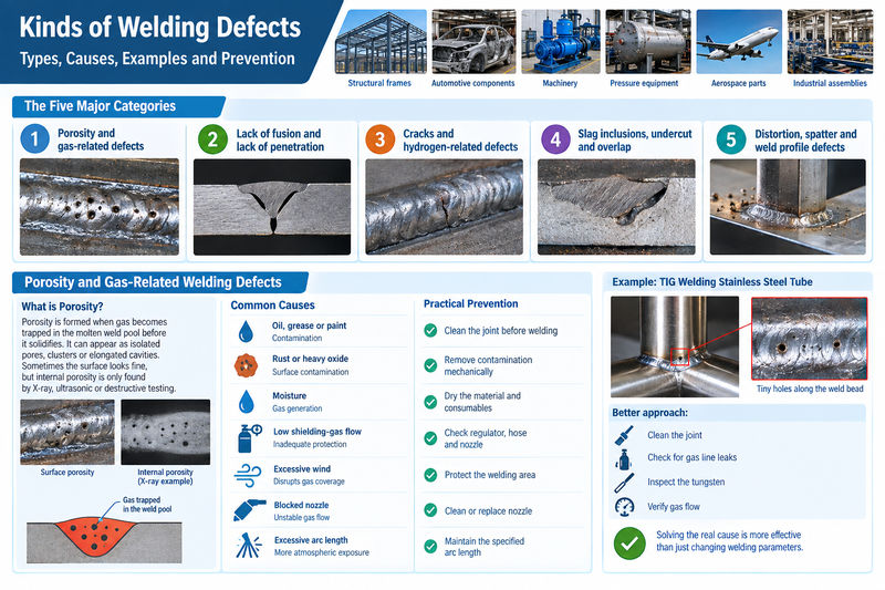
Porosity and Gas-Related Welding Defects
Porosity is one of the easiest welding defects to recognize when it appears on the weld surface. It consists of small cavities or holes created when gas becomes trapped inside molten weld metal before the weld pool solidifies. Porosity may appear as isolated pores, clustered pores, or elongated cavities. In some cases, the surface looks acceptable while internal porosity is only discovered through radiographic, ultrasonic, or destructive examination.
What Causes Porosity?
The most common causes are contamination and inadequate shielding. Oil, grease, rust, paint, moisture, mill scale, and other contaminants can introduce gases into the weld pool. For gas-shielded welding processes such as MIG and TIG, insufficient shielding gas flow can expose the molten metal to atmospheric contamination.
A simplified troubleshooting sequence is useful:
| Possible cause | Typical result | Practical corrective action |
|---|---|---|
| Oil, grease or paint | Scattered pinholes | Clean the joint before welding |
| Rust or heavy oxide | Irregular porosity | Remove contamination mechanically |
| Moisture | Numerous small pores | Dry the material and consumables |
| Low shielding-gas flow | Surface and internal pores | Check regulator, hose and nozzle |
| Excessive wind | Intermittent porosity | Protect the welding area |
| Blocked nozzle | Unstable gas coverage | Clean or replace nozzle |
| Excessive arc length | Increased atmospheric exposure | Maintain the specified arc length |
For example, consider a TIG-welded stainless steel tube that repeatedly develops tiny holes along the weld bead. Increasing amperage may not solve the problem if the actual cause is oil contamination or inadequate argon coverage. Cleaning the joint, checking the gas line for leaks, inspecting the tungsten, and verifying gas flow can be much more effective than randomly changing welding parameters.
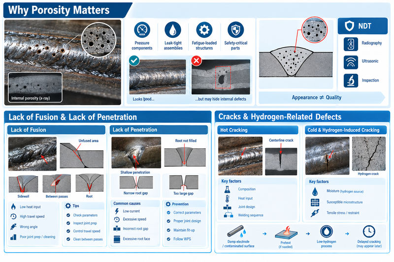
Why Porosity Matters
The severity of porosity depends on its size, concentration, location, and the requirements of the finished component. A small isolated pore may be acceptable under one specification but unacceptable in another application. For pressure-containing components, leak-tight assemblies, fatigue-loaded structures, and safety-critical parts, internal porosity deserves particular attention.
This is why weld quality should not be judged only by appearance. A smooth-looking weld bead can still contain internal discontinuities that require NDT to detect.
Lack of Fusion and Lack of Penetration
Lack of fusion and lack of penetration are two different defects that are often confused.
Lack of fusion occurs when the weld metal does not properly bond with the base metal, a sidewall, or a previous weld pass. Lack of penetration occurs when the weld does not reach the required depth at the joint root. Both can significantly reduce the effective area of a welded joint.
Lack of Fusion
Lack of fusion can occur along the sidewall, between weld passes, or at the root. Typical causes include insufficient heat input, excessive travel speed, an incorrect torch or electrode angle, poor joint preparation, or inadequate cleaning between passes.
For example, imagine a 10 mm thick steel plate welded using multiple passes. If the welder moves too quickly, the molten pool may not adequately melt the sidewall. The weld bead can look visually acceptable, but an unfused boundary may remain underneath the surface.
A practical troubleshooting table looks like this:
| Defect | Common cause | What to check |
|---|---|---|
| Sidewall lack of fusion | Low heat or excessive speed | Current, voltage, travel speed |
| Inter-run lack of fusion | Poor cleaning | Remove slag and oxides |
| Root lack of fusion | Poor torch angle | Joint fit-up and torch position |
| Localized fusion failure | Unstable arc | Power source and consumable condition |
Lack of Penetration
Lack of penetration occurs when weld metal does not penetrate the root of the joint sufficiently. Common causes include low welding current, excessive travel speed, an unsuitable root gap, excessive root face thickness, or incorrect joint preparation.
For a butt joint, joint geometry has a major influence. A narrow root opening may prevent enough molten metal from reaching the root. Conversely, an excessively large root gap can cause excessive penetration or burn-through.
For example, if a drawing specifies a particular root opening and root face but fabrication uses a different joint preparation, the welder may compensate by changing current or travel speed. This can create another problem rather than solving the original one.
How to Prevent Fusion and Penetration Problems
The most reliable approach is to control the entire welding process rather than adjusting only one parameter. Joint preparation, fit-up, current, voltage, travel speed, electrode angle, shielding, interpass cleaning, and welding sequence should all be considered together.
AWS inspection guidance also emphasizes checking actual welding parameters against the applicable welding procedure rather than relying on a welder’s usual settings or personal preference.
Cracks and Hydrogen-Related Welding Defects
Cracking is generally treated with greater concern than many other welding discontinuities because a crack is a sharp discontinuity that can act as a starting point for crack propagation. Welding cracks can develop during solidification or after the weld has cooled, depending on the mechanism involved.
Hot Cracking
Hot cracks, also called solidification cracks in many situations, can form while the weld metal is solidifying. They are often associated with solidification behavior, chemical composition, restraint, weld geometry, and unsuitable welding conditions.
A typical example is a crack developing along the centerline of a weld during solidification. The risk can be influenced by the weld bead shape and the metallurgy of the material.
This means simply increasing welding current is not always an appropriate solution. The filler metal, joint design, heat input, welding sequence, and material composition may all need to be reviewed.
Cold and Hydrogen-Induced Cracking
Hydrogen-related cracking is particularly important when welding susceptible steels. The problem can involve three interacting conditions: diffusible hydrogen, a susceptible microstructure, and sufficient tensile stress or restraint.
Moisture is one possible hydrogen source. Damp electrodes, contaminated surfaces, moisture in the joint, and inappropriate storage of consumables can increase risk. Preheating and controlled low-hydrogen welding practices may be required depending on material, thickness, carbon equivalent, restraint, and applicable procedure requirements.
One important characteristic is that hydrogen-related cracking may not appear immediately after welding. Delayed cracking can occur after the weld has cooled, which means immediate visual inspection alone cannot always provide sufficient assurance.
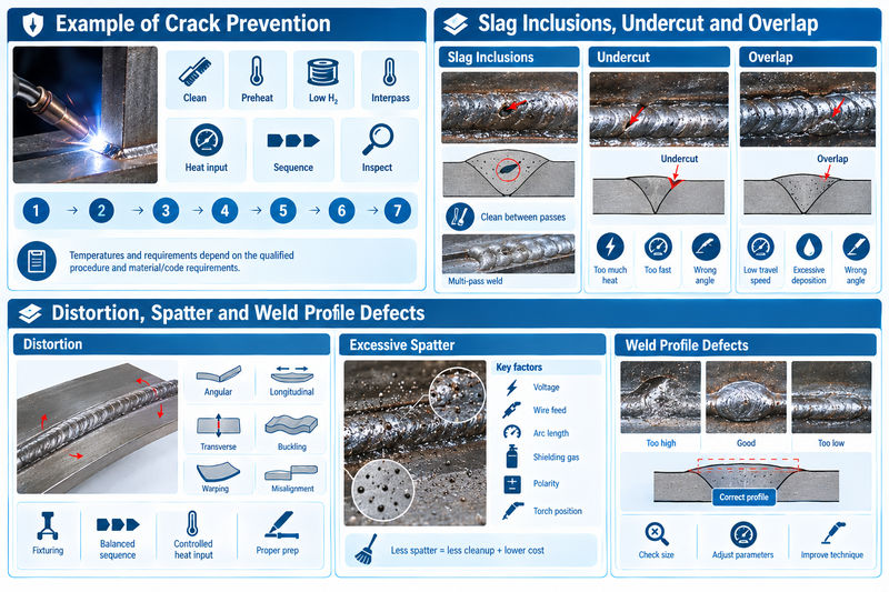
Example of Crack Prevention
Suppose a relatively thick carbon-steel component has high restraint and a material chemistry that makes it susceptible to hardening in the heat-affected zone. A practical production procedure may include:
- Proper joint cleaning
- Controlled preheat
- Dry low-hydrogen consumables
- Correct interpass temperature
- Appropriate welding heat input
- Controlled welding sequence
- Suitable post-weld inspection
The exact temperatures and requirements should come from the qualified welding procedure and applicable material/code requirements rather than from a universal temperature value.
Slag Inclusions, Undercut and Overlap
Some welding defects are caused by material becoming trapped inside the weld, while others result from an incorrect weld profile. Slag inclusions, undercut, and overlap are common examples.
Slag Inclusions
Slag inclusions occur when non-metallic material becomes trapped inside the weld. They are particularly relevant to processes that generate slag, such as SMAW and FCAW, and can become more likely when previous weld passes are not properly cleaned.
A common production example is a multi-pass fillet weld. If the welder deposits the second pass over slag remaining from the first pass, the slag may become trapped instead of floating out of the molten pool.
Between passes, appropriate cleaning may involve chipping, wire brushing, grinding, or other approved methods. Joint geometry also matters because a narrow or poorly designed groove can make it difficult for slag to escape.
Undercut
Undercut is a groove melted into the base metal next to the weld toe that is not adequately filled with weld metal. It creates a change in geometry at the edge of the weld and can become a stress concentration, particularly in fatigue-loaded components.
Common causes include excessive current, excessive travel speed, an incorrect electrode angle, or poor manipulation of the welding torch.
For example, if the current is too high while welding a thin steel bracket, the arc can melt the edge of the base metal faster than the welder can fill it. The result may be a visible groove beside the weld.
| Defect | Typical appearance | Common cause |
|---|---|---|
| Slag inclusion | Dark/non-metallic material inside weld | Poor interpass cleaning |
| Undercut | Groove beside weld toe | Excessive heat or poor angle |
| Overlap | Weld metal extends over base metal without fusion | Low travel speed or excessive deposition |
Overlap
Overlap occurs when weld metal flows beyond the weld toe or edge without properly fusing with the underlying base metal. Unlike simple excess weld metal, overlap represents a fusion problem because the deposited material has not adequately bonded to the surface.
Reducing deposition rate, correcting torch angle, adjusting travel speed, and improving manipulation can help, but the correct solution depends on the welding process and material.
Distortion, Spatter and Weld Profile Defects
Not every welding problem appears as an internal cavity or crack. Some defects are related to heat distortion, excessive spatter, incorrect weld size, or poor weld profile.
Welding Distortion
Welding distortion occurs because the localized heating and cooling of the joint produces uneven thermal expansion and contraction. Thin plates, long welds, asymmetrical assemblies, and highly restrained structures can be particularly challenging.
Common forms include:
- Angular distortion
- Longitudinal shrinkage
- Transverse shrinkage
- Buckling
- Warping
- Misalignment
Consider a 500 mm × 300 mm × 3 mm stainless-steel sheet with a long weld along one edge. If a large amount of heat is concentrated on one side, the welded area contracts during cooling and can pull the sheet out of its original flat position.
Distortion can often be reduced through proper fixturing, balanced welding sequences, intermittent welds where permitted by design, controlled heat input, and appropriate joint preparation.
However, excessive restraint should not simply be used as the solution. High restraint can increase residual stress and may contribute to cracking in susceptible materials.
Excessive Spatter
Spatter consists of small droplets of molten metal expelled from the weld pool and deposited around the welding area. It is especially common in certain MIG/MAG conditions when voltage, wire-feed speed, arc length, shielding gas, polarity, or torch positioning is not properly controlled.
Spatter may not always represent a structural defect, but excessive spatter increases post-weld cleaning time and can indicate unstable welding conditions.
For a production manufacturer, this matters because quality is not only about whether the joint survives a strength test. Excessive cleanup, grinding, rework, and inconsistent weld appearance can also increase manufacturing cost.
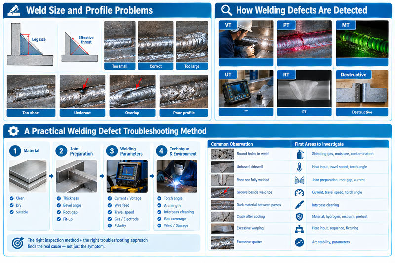
Weld Size and Profile Problems
A weld can also be rejected because it is too small, too large, too short, or has an unacceptable profile. For a fillet weld, for example, the specified leg size or effective throat may be important to the design.
A weld that is substantially oversized is not necessarily a better weld. More deposited metal can mean more heat input, greater distortion, longer welding time, and higher material consumption.
Conversely, an undersized weld may not provide the required load-carrying area.
For this reason, weld inspection should compare the actual weld with the drawing and applicable acceptance requirements instead of judging quality simply by whether the weld “looks strong.”
How Welding Defects Are Detected
Different defects require different inspection methods. Visual inspection is the first and most practical inspection step, but it cannot detect every internal discontinuity.
| Inspection method | Typical application |
|---|---|
| Visual Testing (VT) | Weld size, profile, surface cracks, undercut, overlap, spatter |
| Liquid Penetrant Testing (PT) | Surface-breaking defects on suitable non-porous materials |
| Magnetic Particle Testing (MT) | Surface and near-surface defects in ferromagnetic materials |
| Ultrasonic Testing (UT) | Internal discontinuities such as lack of fusion and some cracks |
| Radiographic Testing (RT) | Internal volumetric discontinuities such as porosity and inclusions |
| Destructive Testing | Cross-section, tensile, bend, macro/micro examination |
No single inspection method is ideal for every defect. For example, visual inspection may identify obvious undercut but cannot reliably prove that a thick weld has complete internal fusion. UT or RT may therefore be required depending on the component and specification.
A Practical Welding Defect Troubleshooting Method
When a welding defect appears repeatedly, simply repairing the visible area may not solve the underlying problem. A better approach is to connect the defect to the process variable most likely responsible.
Start with the material. Check whether the base metal is clean, dry, and suitable for the welding procedure.
Next check the joint preparation. Confirm thickness, bevel angle, root face, root gap, fit-up, alignment, and accessibility.
Then review the welding parameters. Compare actual current, voltage, wire-feed speed, travel speed, shielding gas, electrode type, and polarity with the qualified welding procedure.
Finally inspect the welding technique and environment. Torch angle, arc length, travel direction, interpass cleaning, gas coverage, wind, consumable storage, and welding sequence can all influence defect formation.
For example:
| Observation | First areas to investigate |
|---|---|
| Round holes in weld | Shielding gas, moisture, contamination |
| Unfused sidewall | Heat input, travel speed, torch angle |
| Root not fully welded | Joint preparation, root gap, current |
| Groove beside weld toe | Current, travel speed, torch angle |
| Dark material between passes | Interpass cleaning |
| Crack after cooling | Material, hydrogen, restraint, preheat |
| Excessive warping | Heat input, welding sequence, fixturing |
| Excessive spatter | Arc stability and welding parameters |
This root-cause approach is more effective than repeatedly grinding out the same defect and rewelding it without correcting the process that caused it.
How Xavier Helps Control Welded Part Quality
For customers sourcing custom metal components, welding quality should be considered together with material selection, machining accuracy, joint design, surface finishing, and inspection requirements. A welded assembly may require several processes before it becomes a finished component.
Xavier provides CNC machining and custom metal manufacturing services for customers who need fabricated and machined components produced according to drawings and technical requirements. For welded parts that subsequently require machining, dimensional correction, drilling, milling, turning, or finishing, integrating manufacturing processes can help reduce unnecessary handling between suppliers.
Before production, customers should provide the material grade, part drawings, weld symbols, dimensions, tolerances, quantity, surface requirements, and inspection requirements whenever applicable. These details allow the manufacturing team to determine an appropriate production and inspection process rather than treating every welded component in the same way.
Whether the requirement involves welded steel structures, machined brackets, aluminum components, stainless-steel assemblies, or precision CNC-machined parts, Xavier can evaluate the manufacturing requirements and provide a practical production solution based on the part design.
A good welded component is not simply a weld that looks clean. It is a component in which the joint preparation, welding process, materials, dimensions, inspection, and final application requirements work together.
When welding is combined with precision manufacturing, controlling weld quality is only one part of producing reliable components. At Xavier, we provide professional CNC machining services for customers worldwide, covering custom metal parts, prototypes, and production components. Our capabilities include CNC machining parts, CNC milling, CNC turning, drilling, boring, grinding, and other precision machining processes for materials such as aluminum, stainless steel, brass, copper, titanium, alloy steel, and engineering plastics. For projects involving welded structures or fabricated assemblies, accurate machining of mating surfaces, holes, threads, and mounting features is important for achieving proper fit and reliable performance. We also support custom CNC parts manufacturing according to customer drawings, 3D models, tolerances, material requirements, and surface-finish specifications. Whether you need precision CNC machining for a prototype or CNC metal parts for repeat production, our team can help coordinate machining and quality requirements from the initial design through final inspection. If you are looking for a reliable CNC machining manufacturer for your next project, send us your drawings or specifications for a quotation.
Some of the images and text in this article are collected and compiled from the internet. If there is anything inappropriate, please contact us for processing.