
Custom Plastic Injection Molding: A Practical Guide to Materials, Design, Tooling, and Production
Custom plastic injection molding is one of the most efficient ways to manufacture repeatable plastic components at medium and high production volumes. Unlike CNC machining, which removes material from a solid block, injection molding forms a plastic component by forcing molten polymer into a precisely manufactured mold cavity. Once the material cools and solidifies, the mold opens and the finished part is ejected.
The basic process sounds simple, but producing a plastic part that is dimensionally stable, cosmetically acceptable, mechanically strong, and economical requires much more than simply creating a mold from a 3D model.
Material selection, wall thickness, draft angle, rib and boss geometry, gate location, cooling, shrinkage, tolerances, and mold construction all interact with one another. A design that looks perfect on a CAD screen may still develop sink marks, warpage, short shots, weld lines, flash, or difficult ejection during production.
For this reason, successful custom plastic injection molding begins before the mold is manufactured. The most cost-effective approach is to evaluate the part design, plastic material, expected production volume, tolerance requirements, and cosmetic requirements together.
The following five areas are especially important when developing a custom injection molded plastic part.
1. Choosing the Right Plastic Material for Custom Injection Molding
Material selection is one of the first engineering decisions that should be made because different plastics behave very differently during injection molding. Flow characteristics, shrinkage, stiffness, impact resistance, temperature resistance, chemical resistance, moisture absorption, and surface appearance can all influence the final component.
A plastic that performs well for an electrical enclosure may be completely unsuitable for a high-temperature mechanical component. Likewise, a material that provides excellent strength may be unnecessarily expensive for a simple consumer product.
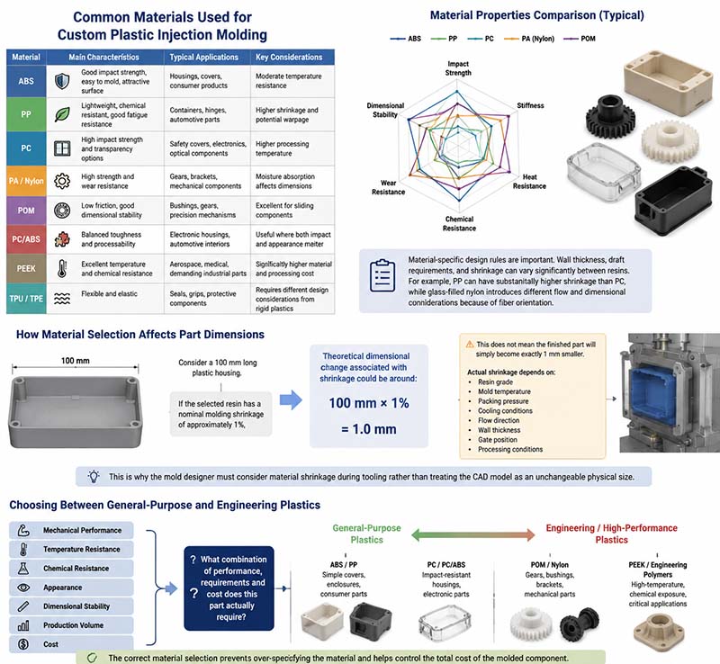
Common Materials Used for Custom Plastic Injection Molding
| Material | Main Characteristics | Typical Applications | Key Considerations |
|---|---|---|---|
| ABS | Good impact strength, easy to mold, attractive surface | Housings, covers, consumer products | Moderate temperature resistance |
| PP | Lightweight, chemical resistant, good fatigue resistance | Containers, hinges, automotive parts | Higher shrinkage and potential warpage |
| PC | High impact strength and transparency options | Safety covers, electronics, optical components | Higher processing temperature |
| PA/Nylon | High strength and wear resistance | Gears, brackets, mechanical components | Moisture absorption affects dimensions |
| POM | Low friction, good dimensional stability | Bushings, gears, precision mechanisms | Excellent for sliding components |
| PC/ABS | Balanced toughness and processability | Electronic housings, automotive interiors | Useful where both impact and appearance matter |
| PEEK | Excellent temperature and chemical resistance | Aerospace, medical, demanding industrial parts | Significantly higher material and processing cost |
| TPU/TPE | Flexible and elastic | Seals, grips, protective components | Requires different design considerations from rigid plastics |
Material-specific design rules are important because wall thickness, draft requirements, and shrinkage can vary significantly between resins. For example, PP can have substantially higher shrinkage than PC, while glass-filled nylon introduces different flow and dimensional considerations because of fiber orientation.
How Material Selection Affects Part Dimensions
Consider a 100 mm long plastic housing.
If the selected resin has a nominal molding shrinkage of approximately 1%, the theoretical dimensional change associated with shrinkage could be around:
100 mm × 1% = 1.0 mm
This does not mean the finished part will simply become exactly 1 mm smaller. Actual shrinkage depends on resin grade, mold temperature, packing pressure, cooling conditions, flow direction, wall thickness, gate position, and processing conditions.
This is why the mold designer must consider material shrinkage during tooling rather than treating the CAD model as an unchangeable physical size.
Choosing Between General-Purpose and Engineering Plastics
For a simple protective cover, ABS or PP may be more economical than an engineering polymer.
For a gear, bushing, or sliding mechanism, POM may be more appropriate because of its low friction and wear characteristics.
For a component exposed to repeated impact, PC may provide a better balance of toughness and dimensional performance.
For a high-temperature application, materials such as PEEK or specialized high-performance polymers may be justified despite their substantially higher material and processing costs.
The correct question is therefore not simply “Which plastic is strongest?” The better question is:
“What combination of mechanical performance, temperature resistance, chemical resistance, appearance, dimensional stability, production volume, and cost does this part actually require?”
This approach prevents over-specifying the material and helps control the total cost of the molded component.
2. Wall Thickness and DFM: Designing a Plastic Part That Can Actually Be Molded
Wall thickness is one of the most influential variables in custom plastic injection molding. It affects filling, cooling time, material consumption, shrinkage, surface appearance, strength, and cycle time.
The most important principle is not simply choosing a particular thickness. It is maintaining a reasonably uniform wall thickness throughout the component.
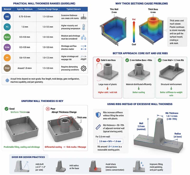
Recent injection molding design references consistently emphasize uniform wall thickness because abrupt thickness changes can produce differential cooling and shrinkage, increasing the risk of sink marks, voids, and warpage.
Practical Wall Thickness Ranges
The following values are useful starting points rather than universal manufacturing specifications:
| Material | Approx. Minimum | Common Design Range | Typical Concern |
|---|---|---|---|
| ABS | 0.75–0.8 mm | 1.5–3.0 mm | Excessive thickness can create sink marks |
| PC | 1.0 mm | 1.5–3.5 mm | Higher viscosity and processing temperature |
| Nylon | 0.5–0.8 mm | 1.0–3.0 mm | Moisture and shrinkage must be considered |
| POM | 0.5–0.8 mm | 1.0–3.0 mm | Shrinkage and flow direction matter |
| PP | 0.6–0.9 mm | 1.0–2.5 mm | Higher shrinkage and warpage risk |
| PEEK | Around 1.0 mm+ | 1.5–3.0 mm | Requires demanding processing conditions |
Actual limits depend on resin grade, flow length, mold design, gate configuration, machine capability, and part geometry.
Why Thick Sections Cause Problems
Suppose a housing has a general wall thickness of 2 mm but contains a solid 6 mm-thick boss.
The 2 mm wall will cool much faster than the 6 mm section. As the thick region remains hot for longer, the plastic continues to shrink internally. This can pull the outer surface inward and create a visible depression known as a sink mark.
A better approach is often to core out the thick boss and use ribs to provide structural support.
For example:
| Design | Approx. Geometry | Expected Result |
|---|---|---|
| Solid 6 mm boss | Large mass of plastic | Higher sink/void risk |
| 2 mm hollow boss + ribs | Material distributed efficiently | Better cooling |
| 2 mm wall + 1.2 mm rib | Structural reinforcement | Better stiffness-to-weight ratio |
This is one of the fundamental differences between designing a machined metal component and designing an injection molded plastic component.
Using Ribs Instead of Excessive Wall Thickness
Ribs increase stiffness without filling the entire area with plastic. A commonly used starting point is to keep rib thickness around 40–70% of the adjacent nominal wall, depending on the resin and cosmetic requirements. Recent design guides commonly recommend approximately 50–70% for many applications.
For a 2.0 mm nominal wall:
2.0 mm × 50% = 1.0 mm
A rib around 1.0–1.4 mm may therefore be a reasonable starting point, subject to material and mold-flow review.
Ribs should also normally include draft and a small radius at the base. A sharp intersection between a rib and the main wall creates a stress concentration and can make mold filling and polishing more difficult.
3. Draft Angles, Ribs, Bosses, and Undercuts
A custom injection molded part must not only fill correctly; it must also come out of the mold without damaging either the part or the tooling.
This is where draft angle becomes critical.
Why Draft Angle Is Necessary
Draft is a slight taper applied to surfaces that run parallel to the mold opening direction.
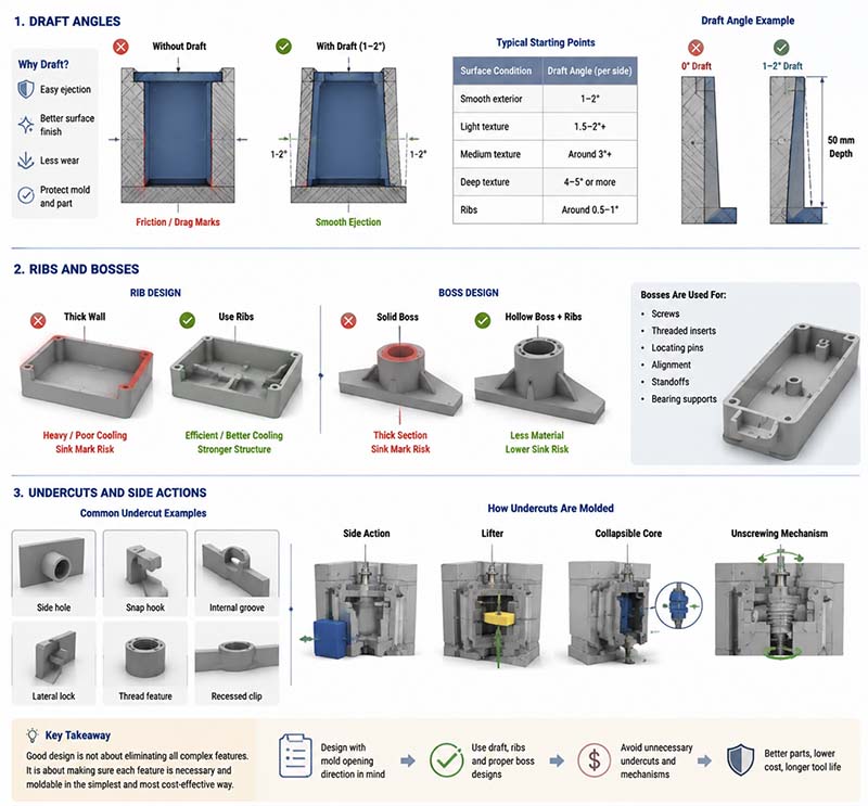
Without sufficient draft, the plastic component can grip the core or cavity surface during ejection. The result may be drag marks, whitening, deformation, ejector damage, or increased mold wear.
For general untextured surfaces, approximately 1–2° is a commonly used practical range. Textured surfaces generally require more draft, and deeper textures can require substantially larger angles.
| Surface Condition | Typical Starting Point |
|---|---|
| Smooth exterior | 1–2° |
| Light texture | 1.5–2°+ |
| Medium texture | Around 3°+ |
| Deep texture | 4–5° or more |
| Ribs | Around 0.5–1° per side |
These numbers should be treated as engineering starting points rather than absolute rules.
Draft Angle Example
Imagine a 50 mm deep internal cavity with a vertical wall.
With insufficient draft, the plastic may shrink onto the core during cooling. When the mold opens, the ejector system must overcome considerable friction.
Adding approximately 1–2° draft changes the geometry so that the wall gradually separates from the core during ejection.
For a cosmetic housing, this small geometric change can make the difference between a clean production part and a surface covered with drag marks.
Boss Design
Bosses are commonly used for:
- Screws
- Threaded inserts
- Locating pins
- Assembly alignment
- Standoffs
- Bearing supports
A common mistake is designing a boss as a solid cylinder. A hollow boss with supporting ribs generally provides a more efficient structure and reduces the amount of plastic concentrated in one location.
For example, instead of creating a 6 mm solid boss connected directly to a 2 mm housing wall, the designer can create a hollow boss and connect it to the housing with two or more ribs.
This reduces localized material thickness and can significantly reduce the risk of sink marks.
Undercuts and Side Actions
Undercuts are features that cannot be released directly along the primary mold-opening direction.
Examples include:
- Side holes
- Snap hooks
- Internal grooves
- Lateral locking features
- Certain threads
- Recessed clips
An undercut does not automatically make a component impossible to mold. However, it may require a side action, lifter, collapsible core, unscrewing mechanism, or another specialized mold mechanism.
The more complicated the mold becomes, the greater the potential tooling cost, maintenance requirements, and cycle-time impact.
Therefore, when designing a custom plastic component, the goal should not necessarily be to eliminate every complex feature. Instead, the goal is to determine whether each feature is functionally necessary and whether it can be redesigned into a simpler molding solution.
4. Injection Mold Design, Gate Location, Cooling, and Production Cycle
The injection mold is the heart of the production system. A well-designed mold does much more than reproduce the external shape of a component.
It controls how plastic enters the cavity, how the material flows, where weld lines appear, how the component cools, how it is ejected, and how consistently dimensions can be maintained.
Gate Location Can Affect the Entire Part
The gate is the location where molten plastic enters the cavity.
Its position affects:
- Flow direction
- Filling balance
- Weld line location
- Air evacuation
- Packing efficiency
- Cosmetic appearance
- Warpage
- Fiber orientation in reinforced materials
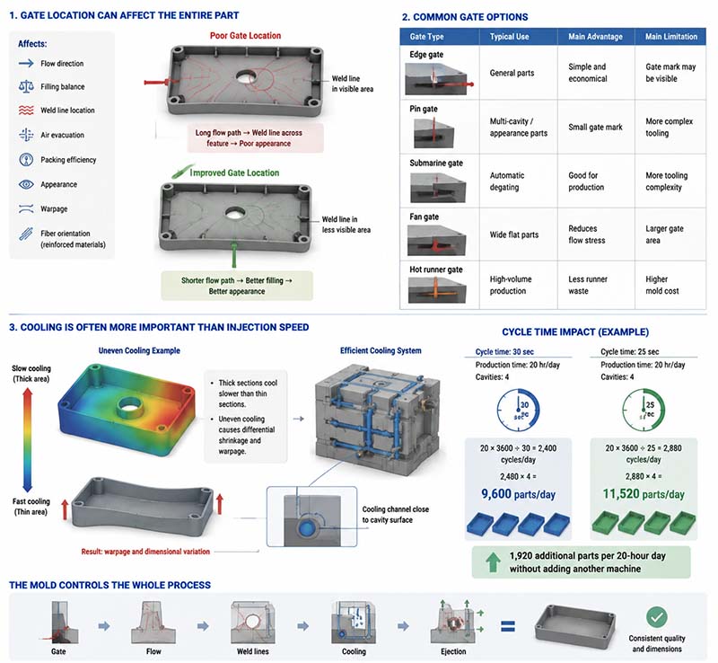
For example, if a large flat cover is gated near one edge, plastic may need to travel across the entire cavity. If the flow fronts meet around a hole or feature, a weld line may appear.
Moving the gate may improve filling and reposition the weld line to a less visible location.
For this reason, gate placement should be considered together with part geometry rather than selected only after the mold design has already been finalized. Recent injection molding design guidance also emphasizes gate location as a major factor in filling and part quality.
Common Gate Options
| Gate Type | Typical Use | Main Advantage | Main Limitation |
|---|---|---|---|
| Edge gate | General parts | Simple and economical | Gate mark may be visible |
| Pin gate | Multi-cavity/appearance parts | Small gate mark | More complex tooling |
| Submarine gate | Automatic degating | Good for production | More tooling complexity |
| Fan gate | Wide flat parts | Reduces flow stress | Larger gate area |
| Hot runner gate | High-volume production | Less runner waste | Higher mold cost |
The best gate depends on the geometry, material, appearance requirements, production volume, and expected cycle time.
Cooling Is Often More Important Than Injection Speed
Once plastic enters the cavity, it must cool sufficiently before ejection.
If one area cools significantly faster than another, the part can develop uneven shrinkage.
For example, a 2 mm wall next to a 5 mm thick section will not cool at the same rate. This difference can create dimensional variation and warpage.
A properly designed cooling system places cooling channels close enough to the cavity surface to remove heat efficiently while maintaining structural integrity in the mold.
In high-volume production, even a small reduction in cycle time can have a major economic effect.
Consider a simplified example:
- Cycle time: 30 seconds
- Production time: 20 hours/day
- 4 cavities
At 30 seconds per cycle:
20 × 3600 ÷ 30 = 2,400 cycles/day
With 4 cavities:
2,400 × 4 = 9,600 parts/day
If the cycle time is reduced from 30 seconds to 25 seconds:
20 × 3600 ÷ 25 = 2,880 cycles/day
2,880 × 4 = 11,520 parts/day
That is approximately 1,920 additional parts per 20-hour production day without adding another machine.
This is why mold cooling, runner design, cavity balance, and ejection efficiency can matter just as much as the mold’s ability to reproduce the geometry.
5. Tolerances, Injection Molding Defects, Quality Control, and Cost
Injection molding can provide excellent repeatability, but plastic parts should not automatically be specified with the same tolerances used for precision CNC-machined metal parts.
Plastic expands and contracts with temperature, absorbs moisture depending on the resin, shrinks during cooling, and may experience orientation-related dimensional changes.
Therefore, tolerances should be based on actual functional requirements.
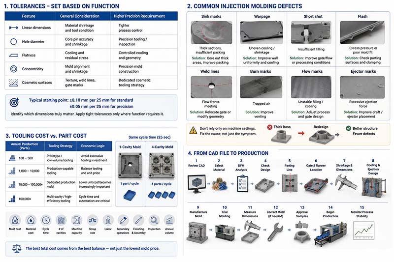
Typical Injection Molding Tolerance Considerations
| Feature | General Consideration | Higher Precision Requirement |
|---|---|---|
| Linear dimensions | Material shrinkage and tool condition | Tighter process control |
| Hole diameter | Core pin accuracy and shrinkage | Precision tooling/inspection |
| Flatness | Cooling and residual stress | Controlled cooling and geometry |
| Concentricity | Mold alignment and shrinkage | Precision mold construction |
| Cosmetic surfaces | Texture, weld lines, gate marks | Dedicated cosmetic tooling strategy |
Some current design references give general tolerance starting points such as approximately ±0.10 mm per 25 mm for standard linear dimensions and tighter values around ±0.05 mm per 25 mm for precision work, but actual achievable tolerances depend heavily on resin, geometry, tooling, and process capability.
The important point is to identify which dimensions actually matter.
For example, a decorative enclosure may not need ±0.05 mm on every outside dimension. A bearing seat, snap-fit interface, or locating hole may require much tighter control.
Applying unnecessarily tight tolerances to every dimension can increase mold machining, inspection, and process-control costs without improving the function of the final product.
Common Injection Molding Defects
| Defect | Typical Cause | Possible Solution |
|---|---|---|
| Sink marks | Thick sections, insufficient packing | Core out thick areas, improve packing |
| Warpage | Uneven cooling/shrinkage | Improve wall uniformity and cooling |
| Short shot | Insufficient filling | Improve gate/flow or processing conditions |
| Flash | Excess pressure or poor mold fit | Check parting surfaces and clamping |
| Weld lines | Flow fronts meeting | Relocate gate or modify geometry |
| Burn marks | Trapped air | Improve venting |
| Flow marks | Unstable filling/cooling | Adjust process and gate design |
| Ejector marks | Excessive ejection force | Improve draft/ejector placement |
Most defects should not be treated simply by changing machine parameters.
If the underlying problem is poor geometry, increasing injection pressure may only move the problem elsewhere.
For example, a thick boss that creates sink marks cannot always be solved by increasing packing pressure. Redesigning the boss and reducing localized thickness may be a more reliable solution.
Tooling Cost vs. Part Cost
One of the most important economic characteristics of custom plastic injection molding is the relationship between tooling investment and per-part cost.
A simplified example:
| Production Quantity | Tooling Strategy | General Economic Logic |
|---|---|---|
| 100–500 | Prototype/low-volume tooling | Avoid excessive tooling investment |
| 1,000–10,000 | Production-capable tooling | Balance tooling and unit price |
| 10,000–100,000+ | Dedicated production mold | Lower unit cost becomes increasingly important |
| 100,000+ | Multi-cavity/high-efficiency tooling | Cycle time and automation become major factors |
These are planning examples rather than fixed industry thresholds.
A simple single-cavity mold may be economical for a low-volume product. For a product requiring hundreds of thousands of parts per year, a multi-cavity mold can dramatically increase output per molding cycle.
For example, if one cavity produces one part every 25 seconds, a four-cavity mold produces four parts during the same cycle.
The tooling cost is therefore not the only number that should be compared. The correct evaluation should include:
- Mold cost
- Material cost
- Cycle time
- Number of cavities
- Machine capacity
- Scrap rate
- Labor
- Secondary operations
- Surface finishing
- Assembly
- Inspection
- Expected annual production volume
A cheaper mold is not necessarily the cheaper manufacturing solution if it produces slower cycles, higher scrap, or more maintenance.
From CAD File to Production
A professional custom plastic injection molding project normally follows a structured sequence:
- Review the 3D CAD model and 2D drawings.
- Select the plastic resin and grade.
- Perform DFM analysis.
- Check wall thickness, draft, ribs, bosses, and undercuts.
- Determine the parting line.
- Evaluate gate and runner locations.
- Review shrinkage and dimensional requirements.
- Design cooling and ejection systems.
- Manufacture the mold.
- Conduct trial molding.
- Measure critical dimensions.
- Correct the mold if necessary.
- Approve samples.
- Begin production.
- Monitor process stability during mass production.
A DFM review before steel is cut is particularly valuable because design changes are generally easier and less expensive before the mold has been manufactured. Recent design references emphasize early DFM analysis as a way to reduce tooling modifications, defects, and production delays.
Custom Plastic Injection Molding Example: A Small Electronics Housing
Consider a plastic electronics enclosure measuring approximately 120 × 80 × 35 mm.
The initial design contains:
- 2.5 mm nominal wall thickness
- Four screw bosses
- Two snap-fit clips
- A rectangular display opening
- Internal reinforcement ribs
- Textured exterior surfaces
- Two mounting holes
A simple CAD model may look production-ready, but the molding review could identify several issues.
First, the 2.5 mm wall should remain reasonably uniform rather than changing abruptly to 5–6 mm around the bosses.
Second, the screw bosses should be hollow and supported with ribs rather than designed as solid columns.
Third, the textured external surface may require more draft than a smooth surface. Using only 0.5° draft could create ejection problems.
Fourth, the gate should be positioned so the flow reaches the major areas of the enclosure without creating an unacceptable weld line near the visible display opening.
Fifth, the snap-fit clips need sufficient draft and appropriate flexibility. A rigid snap feature made from the wrong resin may crack during assembly even if the mold itself works perfectly.
Finally, the most important dimensions should be identified. The display opening and screw-hole locations may require tighter control than the overall exterior dimensions.
This example illustrates why custom plastic injection molding is an engineering process rather than simply a tooling process.
Why Choose Professional Custom Plastic Injection Molding?
A reliable molding supplier should be able to evaluate the entire manufacturing chain rather than simply quote the mold.
The supplier should understand:
- Plastic material behavior
- Mold design
- CNC mold machining
- EDM requirements
- Draft and ejection
- Gate and runner design
- Cooling
- Shrinkage
- Dimensional inspection
- Surface texture
- Secondary machining
- Assembly requirements
- Production volume
For complex plastic parts, CNC machining is also closely connected with injection mold manufacturing. Mold cavities, cores, inserts, electrodes, and precision mold components commonly require accurate CNC machining before assembly and trial molding.
Why Choose Xavier for Custom Plastic Injection Molding?
Xavier provides custom manufacturing support for customers who need plastic components developed from engineering drawings, 3D CAD models, prototypes, or production requirements.
Instead of treating injection molding as simply “making a mold and producing parts,” Xavier focuses on the relationship between part design, material selection, mold construction, dimensional requirements, surface finish, and production volume.
For a new project, customers can provide the 3D CAD file, 2D drawing, target material, estimated annual quantity, critical dimensions, and cosmetic requirements. The engineering team can then evaluate the design for manufacturability and identify potential problems before tooling begins.
This approach is particularly useful when a plastic component contains thin walls, ribs, bosses, snap-fits, textured surfaces, tight dimensional requirements, or complex undercuts.
Whether the requirement is a prototype, a low-volume custom plastic component, or a production part requiring repeatable mass manufacturing, the objective should remain the same: create a mold that is practical to manufacture and a molded part that is stable, functional, and economical to produce.
For companies looking for a long-term custom plastic injection molding partner, Xavier can provide a manufacturing-oriented approach from initial DFM review through tooling, sampling, inspection, and production.
We are an integrated CNC machining manufacturer specializing in custom CNC machining and the production of precision metal parts. Our capabilities cover CNC machining titanium, CNC machining PEEK, and CNC machining nylon, along with a wide range of other materials, including alloy steel, aluminum, brass, bronze, copper, Inconel, Invar 36, low carbon steel, stainless steel, tool steel, ABS, FR4, G-10, PEI, PET, PMMA (acrylic), polycarbonate, polyethylene, polypropylene, POM (acetal), PPSU, PTFE (Teflon), and PVC. We also provide custom machining solutions for robot components, aerospace parts, marine components, automotive parts, medical components, and other precision-engineered parts.
CNC machining titanium manufacturer for your precision components, CNC machining PEEK services for production orders, and CNC machining nylon pricing for your project. Feel free to contact us for more information.
Some of the images and text in this article are collected and compiled from the internet. If there is anything inappropriate, please contact us for processing.