
CNC Machined Heat Sink: A Practical Guide to Materials, Design, Thermal Performance, and Manufacturing
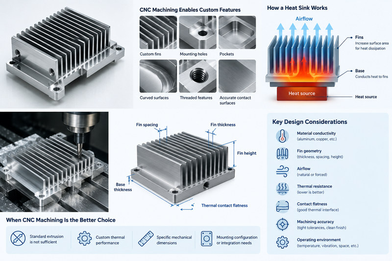
A CNC machined heat sink is a precision thermal-management component manufactured by removing material from an aluminum, copper, or other thermally conductive metal blank. Unlike a standard extruded heat sink, CNC machining allows engineers to create customized fins, mounting holes, pockets, curved surfaces, threaded features, and highly accurate thermal contact surfaces in one component.
The purpose of a heat sink is simple: move heat away from a heat-generating component and transfer that heat to the surrounding air or another cooling medium. The engineering behind it, however, involves material conductivity, fin geometry, airflow, thermal resistance, contact flatness, machining accuracy, and the actual operating environment.
CNC machining becomes particularly useful when a standard extrusion cannot satisfy the required combination of thermal performance, mechanical dimensions, mounting configuration, or product integration. Current CNC heat sink design guidance commonly focuses on fin thickness, fin spacing, fin height, base thickness, thermal contact flatness, and manufacturability because these parameters directly influence both cooling performance and machining cost.
1. Heat Sink Materials: Aluminum vs. Copper
The first major decision in a CNC machined heat sink project is material selection. The material determines how quickly heat spreads through the base and fins, how much the component weighs, how easily it can be machined, and how much the finished heat sink will cost.
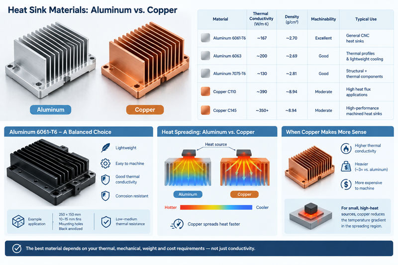
For most custom CNC heat sinks, 6061-T6 aluminum is an excellent starting point because it combines good thermal conductivity, relatively low density, good machinability, corrosion resistance, and strong mechanical properties. Aluminum 6063 is also widely associated with heat-sink applications, while copper is selected when thermal conductivity is more important than weight and cost.
| Material | Approx. Thermal Conductivity | Density | Machinability | Typical Heat Sink Use |
|---|---|---|---|---|
| Aluminum 6061-T6 | ~167 W/m·K | ~2.70 g/cm³ | Excellent | General CNC heat sinks |
| Aluminum 6063 | ~200 W/m·K | ~2.69 g/cm³ | Good | Thermal profiles and lightweight cooling |
| Aluminum 7075-T6 | ~130 W/m·K | ~2.81 g/cm³ | Good | Structural + thermal components |
| Copper C110 | ~390 W/m·K | ~8.94 g/cm³ | Moderate | High heat flux applications |
| Copper C145 | ~350+ W/m·K | ~8.94 g/cm³ | Moderate | High-performance machined heat sinks |
The values above are representative engineering values rather than universal guarantees; actual conductivity varies with alloy, temper, temperature, and material specification. Recent CNC heat sink design references similarly identify 6061 aluminum as a practical general-purpose choice and C110 copper as an option when maximum thermal conductivity is required.
Aluminum 6061-T6 for General CNC Heat Sinks
6061-T6 is often the safest choice when the heat sink needs to perform well without becoming unnecessarily expensive or heavy.
For example, consider a power electronics enclosure requiring a machined heat sink with:
- 250 mm × 150 mm overall dimensions
- Multiple mounting holes
- 10–15 mm fin height
- Integrated electronic-component mounting area
- Black anodized exterior
- Low-to-medium thermal resistance requirement
6061-T6 can provide a good balance between thermal performance and mechanical strength.
Another important advantage is machinability. Aluminum can generally be cut at relatively high spindle speeds and feed rates compared with copper, which helps keep cycle time manageable when dozens of fin channels need to be machined.
When Copper Makes More Sense
Copper has substantially higher thermal conductivity than common aluminum alloys. C110 copper is often listed around 390–400 W/m·K, compared with approximately 167 W/m·K for 6061-T6.
This difference becomes important when heat must spread rapidly from a small, concentrated heat source.
Imagine a 30 mm × 30 mm power module generating 150 W of heat. If the heat source occupies only a small area on a much larger heat sink, the base must spread heat laterally before it reaches the fins. Copper can significantly reduce the temperature gradient within this spreading region.
However, copper is much denser than aluminum:
Copper density ≈ 8.94 g/cm³
6061 aluminum density ≈ 2.70 g/cm³
Therefore, a copper heat sink can weigh more than three times as much as an equivalent aluminum volume. Copper also tends to be more expensive to machine because of its material cost, cutting behavior, burr formation, and lower practical machining efficiency.
For that reason, copper should not automatically be considered “better.” If a 6061 aluminum heat sink can maintain the required component temperature, aluminum may provide the better overall engineering solution.
2. Fin Geometry and CNC Design Rules
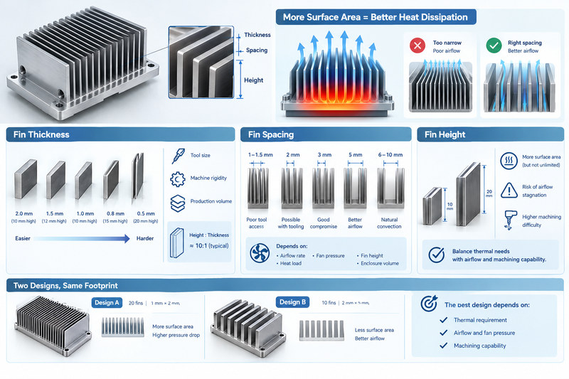
The fins are where much of the heat sink’s exposed surface area is created. Increasing the available surface area allows more heat to transfer from the metal into the surrounding air.
However, simply adding more fins does not automatically produce better cooling.
A heat sink with extremely narrow fin spacing may have a large theoretical surface area but poor airflow. In forced-air applications, the fan may not be able to push enough air through the narrow channels. In natural convection, insufficient spacing can make the situation even worse.
Recent CNC heat sink DFM guidance commonly discusses fin thickness, spacing, height, and aspect ratio because these parameters must satisfy both thermal and machining requirements.
Fin Thickness
For CNC-machined aluminum heat sinks, approximately 1 mm fin thickness is a practical starting point for many designs, although the appropriate value depends on fin height, tool diameter, material, machine rigidity, and production requirements.
For example:
| Fin Design | Typical Machining Consideration |
|---|---|
| 2.0 mm thick × 10 mm high | Very comfortable for CNC machining |
| 1.5 mm thick × 12 mm high | Generally practical |
| 1.0 mm thick × 10 mm high | Possible with controlled tooling/toolpaths |
| 0.8 mm thick × 15 mm high | More demanding |
| 0.5 mm thick × 20 mm high | High-risk for conventional CNC milling |
A thin fin can vibrate under cutting forces. The problem becomes more serious as the fin gets taller.
This is why the height-to-thickness ratio is important. Some CNC design references use approximately 10:1 as a practical upper guideline for conventional aluminum fin machining, while more conservative manufacturing approaches may specify lower ratios.
A 1 mm thick fin that is 10 mm high has a 10:1 ratio.
A 1 mm thick fin that is 20 mm high has a 20:1 ratio and is significantly more difficult to machine reliably.
Fin Spacing
Fin spacing controls both airflow and tool access.
A conceptual comparison:
| Fin Spacing | Cooling / Manufacturing Effect |
|---|---|
| 1–1.5 mm | Difficult tool access, high machining demand |
| 2 mm | Possible with suitable tooling |
| 3 mm | Good compromise for many forced-air designs |
| 5 mm | Better airflow, fewer fins |
| 6–10 mm | Often useful for natural convection |
These are design starting points rather than universal specifications. Actual spacing should be determined by the airflow rate, fan pressure, heat load, fin height, and available enclosure volume.
A common mistake is to maximize the number of fins without considering airflow. Suppose two heat sinks occupy the same footprint:
Design A: 20 fins, 1 mm thick, 2 mm spacing
Design B: 10 fins, 2 mm thick, 5 mm spacing
Design A has more metal surface area, but Design B may allow substantially better airflow. If the system uses a fan, pressure drop through the fin channels becomes an important design variable.
Fin Height
Increasing fin height generally increases surface area, but the improvement is not unlimited.
For example, increasing a fin from 10 mm to 20 mm theoretically adds exposed area. However, if the air near the base becomes stagnant or the enclosure limits airflow, the additional height may not provide the expected reduction in thermal resistance.
Tall fins also increase machining difficulty because the cutting tool must reach deeper into narrow channels. Tool deflection, chatter, chip evacuation, and fin vibration become increasingly important.
Therefore, fin height should be selected based on the thermal requirement and the available airflow and machining capability.
3. Thermal Resistance and Heat Dissipation Performance
The real purpose of a CNC machined heat sink is not simply to look like a heat sink. It must keep the heat-generating component within an acceptable operating temperature.
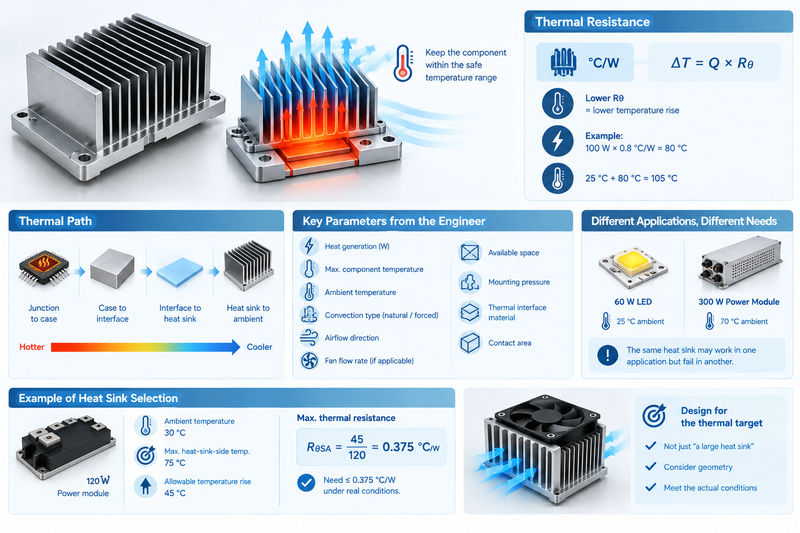
One of the most useful parameters for evaluating heat sink performance is thermal resistance, commonly expressed as:
°C/W
Lower thermal resistance means the heat sink produces a smaller temperature increase for a given heat load.
A simplified relationship is:
Temperature Rise = Heat Power × Thermal Resistance
For example, assume a heat sink has a thermal resistance of:
0.8 °C/W
and the component generates:
100 W
The approximate temperature rise across that thermal resistance is:
100 W × 0.8 °C/W = 80 °C
If the heat sink is operating in a 25 °C ambient environment, the corresponding temperature at that point in the thermal path would be approximately:
25 °C + 80 °C = 105 °C
This is a simplified calculation. Real electronic assemblies include multiple thermal resistances between the semiconductor junction and ambient air. A typical thermal path can include junction-to-case, case-to-interface, interface-to-heat-sink, and heat-sink-to-ambient resistance.
Thermal Resistance Is a System Parameter
A CNC manufacturer cannot determine the required heat sink simply from the physical dimensions of the component.
The engineer should ideally provide:
- Heat generation in watts
- Maximum allowable component temperature
- Ambient temperature
- Natural or forced convection
- Airflow direction
- Fan flow rate, if applicable
- Available installation space
- Mounting pressure
- Thermal interface material
- Contact area
For example, a 60 W LED module operating at 25 °C ambient is a completely different thermal problem from a 300 W industrial power module operating at 70 °C ambient.
The same physical heat sink may work perfectly in the first application but fail in the second.
Example of Heat Sink Selection
Consider a power module generating 120 W.
Assume:
- Ambient temperature = 30 °C
- Maximum heat-sink-side temperature target = 75 °C
- Allowable heat-sink temperature rise = 45 °C
The approximate maximum heat sink-to-ambient thermal resistance would be:
RθSA = 45 / 120 = 0.375 °C/W
That means the cooling system needs to achieve roughly 0.375 °C/W or lower under the actual airflow and installation conditions.
This immediately shows why simply asking for “a large aluminum heat sink” is not enough. The heat sink geometry needs to be designed around the thermal target.
4. Base Flatness, Surface Finish and Thermal Interface
The fin structure receives most of the visual attention, but the heat sink base can be just as important.
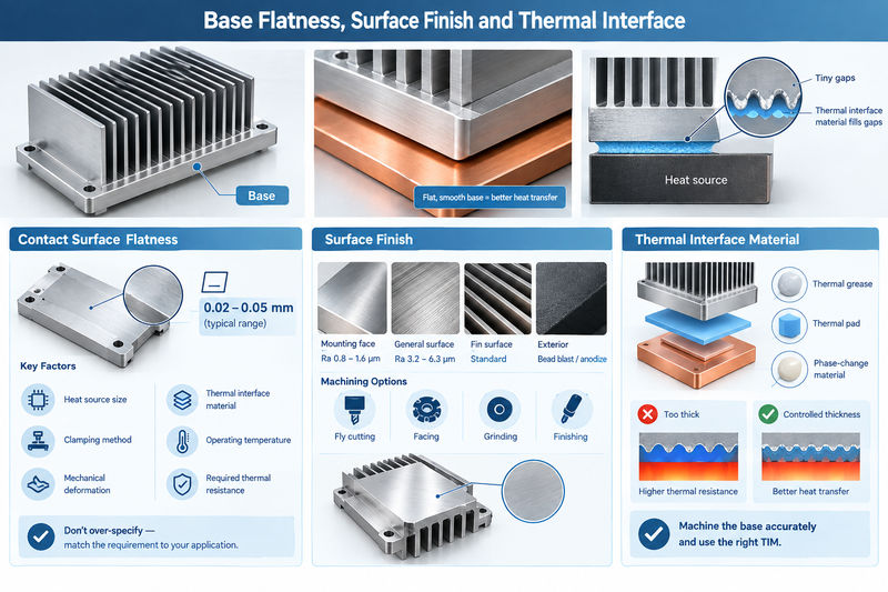
The base is the thermal bridge between the heat-generating component and the fins. If the base is warped, rough, or improperly finished, thermal resistance can increase even if the fin structure is excellent.
Air is a poor thermal conductor compared with aluminum and copper. Tiny gaps between two mating surfaces can therefore become thermal bottlenecks.
Contact Surface Flatness
For a precision CNC heat sink, the mounting surface should be identified as a critical feature on the engineering drawing.
Depending on the application, a flatness specification may be something such as:
0.02–0.05 mm
over a defined mounting area.
Some current CNC heat sink case studies use approximately 0.02 mm flatness for critical thermal mounting regions, while broader DFM guidance commonly recommends controlling the contact surface separately from ordinary machined surfaces.
The important point is not that every heat sink needs 0.02 mm flatness.
Instead, the flatness requirement should be linked to:
- Heat source size
- Thermal interface material
- Clamping method
- Operating temperature
- Mechanical deformation
- Required thermal resistance
Over-specifying flatness can unnecessarily increase machining cost.
Surface Roughness
A typical CNC-machined exterior fin surface does not necessarily need the same finish as the thermal contact surface.
For example:
| Surface | Possible Requirement |
|---|---|
| Thermal mounting face | Ra 0.8–1.6 μm |
| General machined surface | Ra 3.2–6.3 μm |
| Fin surfaces | Standard machined finish may be sufficient |
| Cosmetic exterior | Bead blasted/anodized according to appearance requirement |
The mounting face is usually the critical area because it interfaces with the heat source or thermal interface material.
A fly-cutting, facing, grinding, or finishing operation may be used to achieve a more controlled thermal contact surface.
Thermal Interface Material
Even a precision-machined surface may contain microscopic peaks and valleys. Thermal grease, thermal pads, or phase-change materials can fill these microscopic gaps.
However, the interface material itself has thermal resistance.
This creates an important design principle:
Do not use a thick thermal interface layer to compensate for a poorly controlled heat sink base.
A better approach is to machine the base accurately and then use the appropriate TIM with controlled thickness and mounting pressure.
5. CNC Machining Process, Tolerances and Production Considerations
A CNC machined heat sink is manufactured differently from a simple aluminum block because the machining strategy must protect the fins, thermal base, mounting features, and critical dimensions.
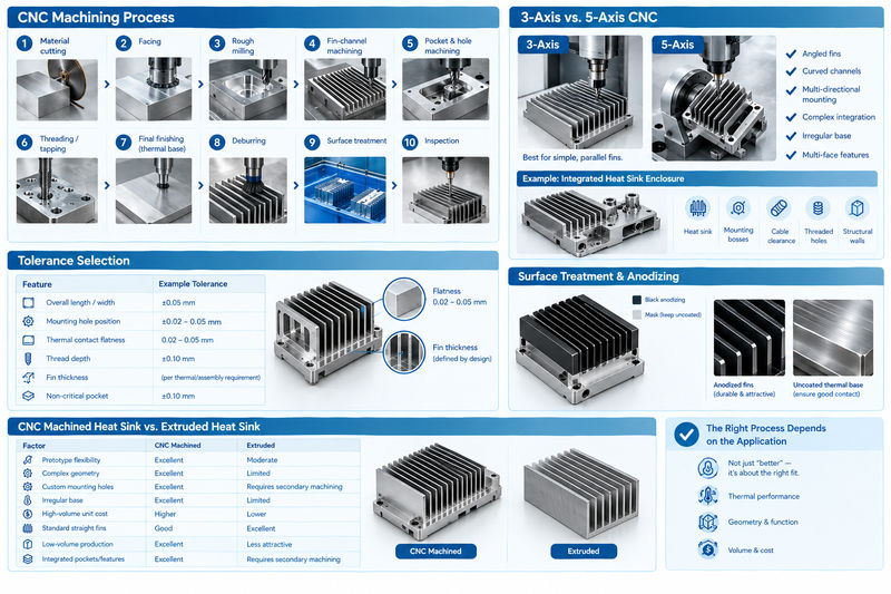
A typical process may include:
- Material cutting
- Initial CNC facing
- Rough milling
- Fin-channel machining
- Pocket and mounting-hole machining
- Threading/tapping
- Precision finishing of the thermal base
- Deburring
- Surface treatment
- Dimensional inspection
The machining sequence matters.
For example, if the final thermal contact surface is machined first and then the workpiece is heavily clamped during fin machining, excessive clamping force may introduce deformation. The final contact face may therefore need to be finished after the major material-removal operations.
3-Axis vs. 5-Axis CNC Machining
A 3-axis CNC machine can manufacture many conventional heat sinks with parallel fins.
A 5-axis machine becomes more useful when the heat sink contains:
- Angled fins
- Curved cooling channels
- Multi-directional mounting features
- Complex enclosure integration
- Irregular base geometry
- Features on several faces
CNC machining is especially valuable when the heat sink must combine thermal and mechanical functions in one component. For example, a power-electronics enclosure may integrate the heat sink, mounting bosses, cable clearance, threaded holes, and structural walls into a single machined aluminum component.
Tolerance Selection
Not every heat sink dimension needs an extremely tight tolerance.
A sensible drawing may divide features into different tolerance levels:
| Feature | Example Tolerance |
|---|---|
| Overall length/width | ±0.05 mm |
| Mounting hole position | ±0.02–0.05 mm |
| Thermal contact flatness | 0.02–0.05 mm |
| Thread depth | ±0.10 mm |
| Fin thickness | According to thermal/assembly requirement |
| Non-critical pocket | ±0.10 mm |
These values are examples for engineering discussion rather than universal machining limits. Current CNC heat sink suppliers commonly advertise tolerances in the ±0.03–0.05 mm range for suitable geometries, while critical thermal surfaces may require separate flatness specifications.
The key is to specify tight tolerances only where they affect thermal contact, mounting alignment, airflow, or assembly.
Surface Treatment and Anodizing
Aluminum heat sinks are frequently anodized for corrosion resistance, appearance, and surface durability.
Black anodizing is also commonly selected for external heat sink surfaces because the finish can increase emissivity and provide a durable protective layer.
However, the thermal contact face needs special attention.
If the heat source directly contacts the aluminum base, the anodized layer may not be desirable on that interface. A practical manufacturing approach can be to mask the thermal contact surface during anodizing and leave the critical mounting region in the required machined condition.
The drawing should clearly identify which surfaces are to be anodized and which surfaces must remain uncoated.
CNC Machined Heat Sink vs. Extruded Heat Sink
CNC machining is not automatically better than extrusion. The correct process depends on the application.
| Factor | CNC Machined Heat Sink | Extruded Heat Sink |
|---|---|---|
| Prototype flexibility | Excellent | Moderate |
| Complex geometry | Excellent | Limited by extrusion profile |
| Custom mounting holes | Excellent | Requires secondary machining |
| Irregular base | Excellent | Limited |
| High-volume unit cost | Higher | Usually lower |
| Standard straight fins | Good | Excellent |
| Low-volume production | Excellent | Less attractive for custom profiles |
| Integrated pockets/features | Excellent | Requires secondary machining |
Extrusion is often more economical for high-volume heat sinks with a simple, continuous fin profile. CNC machining becomes attractive when the geometry is unique, the volume is low to medium, the thermal interface requires precision, or the heat sink needs to be integrated with another mechanical component.
Practical Example: Designing a CNC Aluminum Heat Sink
Consider a custom heat sink for a 100 W industrial controller.
The initial requirements are:
| Parameter | Example Requirement |
|---|---|
| Heat generation | 100 W |
| Ambient temperature | 30 °C |
| Material | 6061-T6 aluminum |
| Cooling method | Forced air |
| Overall size | 180 × 120 mm |
| Fin height | 15 mm |
| Fin thickness | 1.5 mm |
| Fin spacing | 3–4 mm |
| Base thickness | 6 mm |
| Mounting surface | Controlled flatness |
| Mounting holes | 4 × threaded holes |
| Exterior finish | Black anodized |
| Thermal contact face | Masked during anodizing |
The design process would begin with the thermal target rather than the appearance.
The engineer would calculate the required thermal resistance, determine the approximate fin area, check airflow direction, then select fin thickness and spacing that can actually be manufactured.
The CAD model should also identify the critical mounting face, mounting-hole positions, airflow direction, and surfaces requiring anodizing.
During CNC production, roughing and fin machining would be separated from the final thermal-face finishing operation. After machining, the part would be deburred and inspected before anodizing. The thermal contact surface would then be protected from coating if required.
This approach avoids a common mistake: designing an impressive-looking fin structure first and attempting to solve thermal and manufacturing problems afterward.
Common CNC Machined Heat Sink Design Mistakes
Too Many Fins
More fins do not automatically mean better cooling. Extremely narrow passages can restrict airflow and increase machining time.
Fins That Are Too Thin
Thin, tall fins can vibrate during machining. The result may be inconsistent fin thickness, chatter marks, burrs, or even broken fins.
Ignoring the Thermal Base
A heat sink with excellent fins but a warped contact surface can still have poor thermal performance.
Excessive Tolerances
Specifying ±0.01 mm on every feature can increase machining time and inspection cost without improving cooling performance.
Applying Anodizing to Every Surface
The thermal contact surface may need to remain uncoated depending on the assembly and TIM configuration.
Designing Without Manufacturing Input
A CFD-optimized geometry may not always be practical for CNC machining. Tool access, cutter diameter, fin aspect ratio, chip evacuation, workholding, and inspection must be considered before production.
How to Prepare a CNC Machined Heat Sink RFQ
When requesting a quotation, providing only a 3D CAD model may not be enough.
A better RFQ package should include:
- STEP/STP or equivalent 3D model
- 2D engineering drawing
- Material specification
- Heat generation in watts
- Maximum operating temperature
- Ambient temperature
- Airflow conditions
- Critical mounting surface
- Flatness requirement
- Surface roughness requirement
- Thread specifications
- Anodizing or other finish
- Quantity
- Inspection requirements
This information allows the CNC manufacturer to distinguish between cosmetic features and genuinely functional thermal features. Current heat-sink RFQ guidance similarly emphasizes defining thermal requirements and identifying which surfaces control thermal performance rather than relying on the CAD model alone.
Why Choose Xavier for CNC Machined Heat Sinks?
For a custom CNC machined heat sink, the best manufacturing partner should understand both machining and thermal requirements.
Xavier provides CNC machining solutions for custom metal components, with capabilities suitable for aluminum and copper heat sinks, precision mounting surfaces, complex fin structures, threaded holes, pockets, and integrated mechanical features.
For a prototype, the priority may be rapid design verification. For batch production, the focus shifts toward repeatability, machining efficiency, inspection, and consistent surface treatment.
A practical Xavier heat sink project can therefore begin with the customer’s CAD drawing and thermal requirements, followed by DFM review of the fin geometry, material, base thickness, mounting features, machining accessibility, tolerance requirements, and surface finish.
The goal is not simply to manufacture a metal component with fins. It is to produce a heat sink that can transfer heat effectively, fit the intended assembly, maintain the required dimensional accuracy, and remain economical to manufacture.
For applications involving power electronics, LED systems, industrial controllers, communication equipment, motor drives, automotive electronics, or other heat-generating assemblies, a properly engineered CNC machined heat sink can provide a practical solution when standard heat sinks cannot satisfy the required geometry or thermal interface.
The most effective approach is to design the thermal performance and manufacturing process together. Choose the material according to the heat load, optimize fin geometry according to airflow, control the thermal contact surface, and avoid unnecessarily difficult CNC features. With these factors considered from the beginning, CNC machining can produce highly customized heat sinks with repeatable thermal and mechanical performance.
We are an integrated CNC machining manufacturer specializing in custom CNC machining and the production of precision metal components. Our capabilities cover a wide range of materials, including alloy steel, aluminum, brass, bronze, copper, Inconel, Invar 36, low carbon steel, stainless steel, titanium, tool steel, ABS, FR4, G-10, nylon, PEEK, PEI, PET, PMMA (acrylic), polycarbonate, polyethylene, polypropylene, POM (acetal), PPSU, PTFE (Teflon), and PVC. We provide professional CNC machining aluminum, CNC machining PEEK, and CNC machining titanium for robotics, aerospace components, marine parts, automotive components, medical parts, and other precision applications.
As an experienced CNC machining aluminum manufacturer, we support CNC machining PEEK services for production requirements and can provide CNC machining titanium pricing based on your project specifications. Feel free to contact us for professional CNC machining solutions and a customized quotation.
CNC Machined Heat Sink FAQs
1. What is a CNC machined heat sink?
A precision heat sink manufactured by CNC milling to remove heat from electronic components.
2. What material is best for CNC heat sinks?
6061-T6 aluminum is a popular choice for its good thermal conductivity, low weight, and excellent machinability. Copper is preferred for higher thermal conductivity.
3. Can CNC machining make thin heat sink fins?
Yes. CNC milling can produce thin, closely spaced fins, but fin thickness and height must be designed according to tooling and machining limitations.
4. How does fin spacing affect heat dissipation?
Proper fin spacing allows sufficient airflow. Extremely narrow spacing can restrict airflow and reduce actual cooling performance.
5. Does a CNC heat sink need a flat base?
Yes. A flat, smooth thermal contact surface helps minimize gaps between the heat sink and component, improving heat transfer.
6. Can CNC machined heat sinks be anodized?
Yes. Aluminum heat sinks can be anodized for corrosion protection, appearance, and durability. The thermal contact surface can be masked when necessary.
Some of the images and text in this article are collected and compiled from the internet. If there is anything inappropriate, please contact us for processing.