
Chamfer vs Fillet: Understanding the Real Difference in CNC Machining and Product Design
In CNC machining and mechanical design, edge treatment is more than just cosmetic finishing. The choice between a chamfer and a fillet directly affects manufacturability, part strength, assembly performance, tooling efficiency, safety, and production cost. Engineers, machinists, and product designers constantly decide whether an edge should be beveled or rounded based on function and manufacturing requirements.
This guide explains the practical differences between chamfer and fillet from a CNC machining perspective, including engineering applications, machining considerations, CAD modeling, tooling impact, and real-world examples.
What Is a Chamfer?
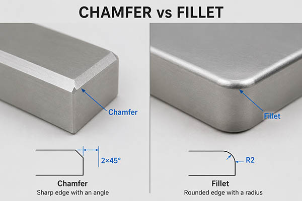
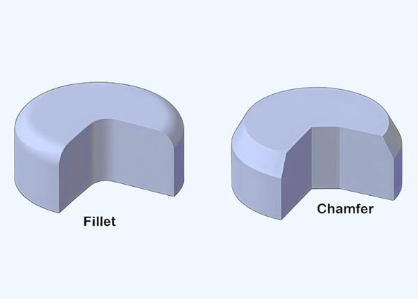
A chamfer is a beveled edge created by cutting away a sharp corner at an angle. The most common chamfer angle is 45 degrees, although other angles such as 30° or 60° are frequently used depending on design requirements.
Typical Chamfer Formula
For a 45° chamfer:
- 1 × 45°
- 2 × 45°
- 0.5 × 45°
This means the edge is cut equally along two adjacent surfaces.
Common Uses of Chamfers
| Application | Purpose |
|---|---|
| Bolt holes | Easier screw insertion |
| Mechanical edges | Remove burrs |
| Assembly parts | Improve alignment |
| Weld preparation | Edge beveling |
| Aerospace parts | Reduce sharp corners |
Chamfers are extremely common in CNC machining because they are easy and fast to manufacture using standard chamfer mills or spot drills.
Example
A CNC aluminum housing may use a 1mm × 45° chamfer around all outer edges to:
- Remove dangerous sharp corners
- Improve aesthetics
- Simplify anodizing finish consistency
- Speed up assembly
What Is a Fillet?
A fillet is a rounded internal or external corner that replaces a sharp edge with a radius.
In engineering drawings, fillets are normally defined using radius dimensions such as:
- R0.5
- R2
- R5
Fillets can exist on both interior and exterior edges.
Common Uses of Fillets
| Application | Purpose |
|---|---|
| Structural parts | Reduce stress concentration |
| Consumer products | Improve ergonomics |
| Molded plastic parts | Improve material flow |
| Aerospace brackets | Increase fatigue resistance |
| Automotive parts | Prevent cracking |
Unlike chamfers, fillets distribute stress more evenly across surfaces.
Example
An aerospace titanium bracket may use R3 fillets around internal corners to reduce crack propagation caused by cyclic loading.
Geometric Differences Between Chamfers and Fillets
| Feature | Chamfer | Fillet |
|---|---|---|
| Shape | Angled edge | Rounded edge |
| Typical Dimension | Angle + distance | Radius |
| Machining Speed | Faster | Slower |
| Stress Reduction | Moderate | Excellent |
| Tooling Complexity | Low | Medium |
| Appearance | Sharp and technical | Smooth and organic |
| Cleaning | Easier | Can trap debris internally |
| Cost | Lower | Slightly higher |
The geometric difference may seem small, but mechanically the performance difference can be significant.
Chamfer vs Fillet in CNC Machining
In CNC machining, chamfers are generally easier and cheaper to produce than fillets.
Why Chamfers Are Easier
Chamfers can often be machined in a single pass using:
- Chamfer mills
- Countersink tools
- Spot drills
A CNC machine only needs simple linear movement along the edge.
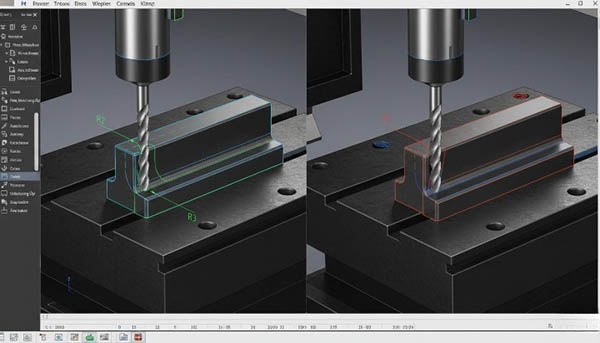
Why Fillets Require More Machining Time
Fillets require:
- Ball nose end mills
- Radius cutters
- 3-axis or 5-axis interpolation
- Smoother toolpaths
Internal fillets especially increase machining complexity because cutter radius limitations must be considered.
CNC Machining Example
| Feature | Chamfer | Fillet |
|---|---|---|
| Tool | Chamfer mill | Ball nose end mill |
| Machining Time | 15 sec | 45 sec |
| Programming Complexity | Low | Medium |
| Surface Blending | Minimal | Important |
For high-volume machining, chamfers often reduce cycle time significantly.
Toolpath and Manufacturing Complexity
Toolpath generation differs substantially between chamfered and filleted edges.
Chamfer Toolpath
- Straight linear motion
- Minimal CAM calculation
- Less machine interpolation
- Lower vibration risk
Fillet Toolpath
- Continuous curved interpolation
- More tool engagement variation
- Greater smoothing requirements
- Increased machine acceleration/deceleration
In high-speed machining, large fillets can improve cutter motion smoothness, but tiny fillets may create excessive tool movement.
CAM Software Considerations
Popular CAM systems like:
- Fusion 360
- Mastercam
- HyperMill
- SolidCAM
usually generate chamfer operations faster than complex 3D fillet finishing strategies.
Strength and Stress Distribution
One of the most important engineering differences between chamfers and fillets is stress concentration.
Stress Concentration Problem
Sharp corners create stress risers where cracks can initiate.
Fillets reduce these stress peaks dramatically.
Engineering Comparison
| Edge Type | Stress Concentration Factor |
|---|---|
| Sharp Corner | Very High |
| Chamfer | Medium |
| Fillet | Low |
Real Engineering Example
In aerospace aluminum components:
- Sharp corners may fail after repeated vibration cycles
- Filleted corners improve fatigue life substantially
Finite Element Analysis (FEA) often shows stress reductions of 20%–50% when proper fillets are added.
This is why fillets dominate in:
- Aircraft structures
- Automotive suspension parts
- High-load CNC components
Surface Finish Considerations
Surface quality differs between chamfers and fillets.
Chamfers
Advantages:
- Cleaner visible edge lines
- Easier deburring
- More precise appearance
Disadvantages:
- Can still feel sharp
- Reflects light harshly
Fillets
Advantages:
- Smooth tactile feel
- Premium consumer-product appearance
- Better coating transitions
Disadvantages:
- Harder polishing internally
- May require finer finishing passes
For anodized CNC aluminum products, small fillets often produce more visually appealing transitions.
Cost Comparison in Production
Production cost is a major factor in edge design.
Cost Factors
| Factor | Chamfer | Fillet |
|---|---|---|
| Tool Cost | Lower | Higher |
| Programming | Easier | Harder |
| Machining Time | Faster | Slower |
| Inspection | Simpler | More complex |
| Tool Wear | Lower | Higher |
Manufacturing Reality
For mass production:
- Chamfers often reduce cycle time by 5%–15%
- Complex fillets may increase finishing operations
This is especially important in:
- Automotive production
- CNC prototyping
- Electronics enclosures
Assembly and Fitment Applications
Chamfers are heavily used for assembly alignment.
Examples
| Part Type | Edge Choice |
|---|---|
| Bolt insertion | Chamfer |
| Bearing seats | Chamfer |
| Press-fit components | Chamfer |
| Ergonomic handles | Fillet |
| Structural ribs | Fillet |
A chamfer helps guide components into place during assembly.
This is why screws, pins, and shafts frequently use lead-in chamfers.
Safety and Ergonomics
Fillets are generally safer for human contact.
Consumer Product Examples
| Product | Preferred Edge |
|---|---|
| Smartphones | Fillet |
| Medical devices | Fillet |
| Industrial tooling | Chamfer |
| Aerospace panels | Mixed |
Rounded edges reduce injury risk and improve comfort.
Chamfers may still feel aggressive on handheld products.
Chamfer vs Fillet in Injection Molding
Plastic injection molding strongly favors fillets internally.
Why Fillets Matter in Molding
Fillets improve:
- Resin flow
- Cooling consistency
- Structural integrity
- Mold filling
Sharp internal corners can cause:
- Sink marks
- Stress cracking
- Weak weld lines
Recommended Fillet Guidelines
| Wall Thickness | Recommended Internal Radius |
|---|---|
| 2 mm | 0.5–1 mm |
| 4 mm | 1–2 mm |
| 6 mm | 2–3 mm |
Most molded parts combine:
- External chamfers for appearance
- Internal fillets for strength
Welding Preparation and Edge Treatments
Chamfers are commonly used in welding preparation.
Common Weld Chamfers
| Weld Type | Chamfer Angle |
|---|---|
| V-groove | 30°–45° |
| Bevel weld | 37.5° |
| Pipe welding | 37.5° |
Chamfered edges allow:
- Better weld penetration
- Improved filler material access
- Stronger joint formation
Fillets in welding refer to a completely different concept: the fillet weld itself.
GD&T and Engineering Drawings
Proper dimensioning is essential.
Chamfer Notation
Examples:
- 1 × 45°
- C1
- 2 × 30°
Fillet Notation
Examples:
- R2
- R5
- FULL R
Common Drawing Errors
| Error | Result |
|---|---|
| Undefined radius | Machining confusion |
| Overly small fillets | Tool access problems |
| Missing chamfer angle | Production inconsistency |
Designers should always consider machinability when specifying edge geometry.
Common Materials and Edge Design Choices
Different materials benefit from different edge styles.
| Material | Preferred Edge |
|---|---|
| Aluminum | Chamfer + small fillet |
| Stainless steel | Fillet for stress areas |
| Titanium | Large fillets |
| Plastics | Fillets |
| Brass | Decorative chamfers |
Titanium machining especially benefits from larger radii because sharp corners increase heat concentration during cutting.
When to Choose Chamfer or Fillet in Real Projects
Choose Chamfers When:
- You need lower machining cost
- Fast production matters
- Assembly guidance is required
- Deburring is the priority
- The part is mainly mechanical
Choose Fillets When:
- Stress reduction matters
- Fatigue resistance is critical
- Human interaction is involved
- A premium appearance is desired
- Smooth airflow or fluid flow matters
Hybrid Approach
Many CNC machined parts combine both:
- Chamfers for assembly edges
- Fillets for structural corners
This hybrid strategy is extremely common in aerospace and automotive industries.
Real CNC Machining Example: Aluminum Electronics Housing
Part Requirements
- Material: 6061 Aluminum
- Surface: Black anodized
- Production volume: 5,000 units/month
Edge Strategy
| Area | Edge Type |
|---|---|
| Outer visible edges | R1 fillet |
| Screw holes | 0.5 × 45° chamfer |
| Internal pockets | R2 fillet |
| Connector openings | Chamfer |
Result
Benefits achieved:
- Better user feel
- Reduced machining marks
- Easier assembly
- Improved anodized appearance
This demonstrates how practical engineering usually combines both edge treatments instead of choosing only one.
Why CNC Manufacturers Often Recommend Optimized Edge Design
Poor edge design increases:
- Tool wear
- Cycle time
- Programming complexity
- Inspection difficulty
Experienced CNC manufacturers often modify customer CAD models slightly to improve manufacturability while maintaining functional requirements.
For example:
- Increasing tiny fillet radii
- Simplifying unnecessary edge breaks
- Standardizing chamfer sizes
These small adjustments can significantly reduce manufacturing cost.
Xavier Precision Machining Recommendation
At Xavier, edge treatment optimization is considered an important part of DFM (Design for Manufacturability). Whether a customer needs high-strength aerospace components, cosmetic consumer-product housings, or precision industrial parts, choosing the correct chamfer or fillet strategy can improve both performance and manufacturing efficiency.
Xavier engineering teams regularly help customers:
- Optimize CNC machining cycle times
- Improve structural reliability
- Reduce unnecessary tooling costs
- Enhance anodizing and finishing quality
- Simplify assembly processes
For CNC machined aluminum, stainless steel, titanium, brass, and engineering plastics, proper edge geometry is often the difference between an average part and a high-performance product.
We are an integrated industrial and trading company specializing in CNC machining services, focusing on custom CNC machining and precision manufacturing of various metal components. We support CNC anodizing surface finishing, CNC electroless nickel plating surface finishing, and CNC passivation surface finishing. As a CNC anodizing surface finishing manufacturer, we provide high-volume CNC electroless nickel plating surface finishing services. Contact us today to get the best CNC passivation surface finishing pricing.
Some of the images and text in this article are collected and compiled from the internet. If there is anything inappropriate, please contact us for processing.