
How to Drill and Tap a Hole: A Complete CNC Machining Guide
Drilling and tapping are two fundamental operations in CNC machining and metal fabrication. They are commonly used to create threaded holes for bolts, screws, studs, and other fasteners. Although the processes may appear straightforward, producing an accurate threaded hole requires careful control of drill size, tapping depth, cutting speed, feed rate, tool selection, and material properties.
For CNC manufacturers, an incorrectly drilled or tapped hole can lead to loose fasteners, damaged threads, assembly problems, or even component failure. These issues become particularly important when machining aluminum, stainless steel, alloy steel, titanium, and other engineering materials.
This guide explains how to drill and tap a hole step by step, covering hole preparation, tap drill sizes, thread standards, CNC tapping methods, cutting parameters, common defects, and inspection techniques. It also provides practical examples to help engineers, machinists, and purchasing professionals understand how to achieve reliable threaded holes in precision-machined components.
10 Important Topics About How to Drill and Tap a Hole
- Understanding the difference between drilling and tapping.
- Selecting the correct drill bit and tap.
- Determining the correct tap drill size.
- Understanding thread types, pitches, and specifications.
- Preparing the workpiece and locating the hole accurately.
- Drilling the correct hole depth and diameter.
- Choosing the right tapping method and cutting parameters.
- Understanding blind holes versus through holes.
- Avoiding common drilling and tapping problems.
- Measuring and inspecting finished threaded holes.
Detailed Guide to Drilling and Tapping a Hole
1. Understanding the Difference Between Drilling and Tapping
Drilling and tapping are two separate machining operations that work together to produce an internal threaded hole.
Drilling is the process of removing material from a workpiece using a rotating drill bit. It creates a cylindrical hole with a specified diameter and depth. The drilled hole must be smaller than the nominal diameter of the screw because additional material is needed to form the internal threads.
Tapping is the process of cutting or forming internal threads inside the previously drilled hole. A tap has specially designed cutting edges or forming lobes that create the thread profile required for a particular fastener.
For example, when manufacturing an aluminum mounting bracket with an M8 threaded hole, the machinist first drills a 6.8 mm hole and then uses an M8 × 1.25 tap to create the internal thread.
| Operation | Main purpose | Typical tool |
|---|---|---|
| Drilling | Creates the initial hole | Twist drill |
| Chamfering | Removes sharp edges and creates an entry | Chamfer mill or countersink |
| Tapping | Produces internal threads | Cutting or forming tap |
| Deburring | Removes burrs around the opening | Deburring tool |
In CNC machining, these operations are frequently combined in one machining program. Correct coordination between drilling depth, tool positioning, and tapping depth helps ensure that the finished hole meets the engineering drawing.
2. Selecting the Correct Drill Bit and Tap
Choosing the correct cutting tools is essential for producing accurate threaded holes. Different materials require different tool geometries, coatings, and cutting-edge designs.
A standard high-speed steel (HSS) drill is suitable for many general-purpose applications, while cobalt HSS and carbide drills are often selected for harder materials or higher-production environments.
The tap must also match the thread specification and workpiece material.
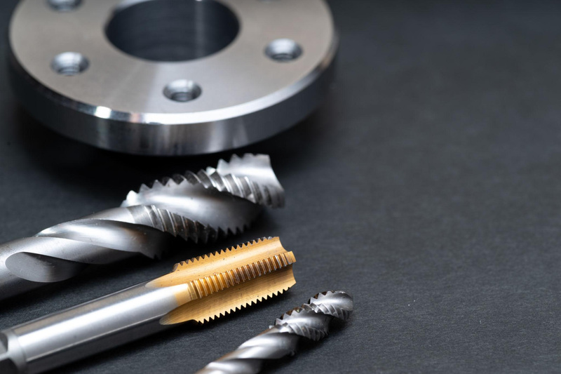
Common drill bit options:
- HSS drill bits: Economical and suitable for mild steel, aluminum, brass, and general-purpose machining.
- Cobalt drill bits: Provide better heat resistance and are commonly used for stainless steel and alloy steel.
- Solid carbide drills: Offer high rigidity, wear resistance, and dimensional consistency in CNC production.
- Spot drills: Create accurate starting points and reduce drill walking, particularly when hole-position accuracy is important.
Common tap options:
- Straight-flute taps: Suitable for many general-purpose applications, particularly through holes in materials that produce manageable chips.
- Spiral-point taps: Push chips forward and are commonly used for through-hole tapping.
- Spiral-flute taps: Pull chips upward, making them useful for blind holes where chip evacuation is important.
- Forming taps: Displace material rather than cutting it, producing threads without conventional chips. They require suitable ductile materials and a correctly sized pilot hole.
For aluminum 6061-T6, a sharp spiral-flute cutting tap or a suitable forming tap can provide good results. For stainless steel 304, machinists should prioritize sharp, material-specific tooling, effective lubrication, and controlled cutting conditions to reduce work hardening and tool wear.
3. Determining the Correct Tap Drill Size
Selecting the correct tap drill size is one of the most important steps in the entire process. If the drilled hole is too small, tapping torque increases significantly, potentially causing tap breakage. If the hole is too large, the resulting threads may have insufficient engagement and reduced load capacity.
For general cutting taps, approximately 75% thread engagement is a common starting point. However, the final drill size should always follow the tap manufacturer’s recommendations and the engineering requirements.
The basic metric formula is:
[ D{\text{drill}} \approx D{\text{thread}}-P ]
Where:
- (D_{\text{drill}}) = recommended tap drill diameter
- (D_{\text{thread}}) = nominal thread diameter
- (P) = thread pitch
For example, an M8 × 1.25 thread requires:
[ 8-1.25=6.75\text{ mm} ]
A standard 6.8 mm drill is commonly selected.
Common metric tap drill sizes
| Thread size | Pitch | Tap drill diameter |
|---|---|---|
| M3 × 0.5 | 0.5 mm | 2.5 mm |
| M4 × 0.7 | 0.7 mm | 3.3 mm |
| M5 × 0.8 | 0.8 mm | 4.2 mm |
| M6 × 1.0 | 1.0 mm | 5.0 mm |
| M8 × 1.25 | 1.25 mm | 6.8 mm |
| M10 × 1.5 | 1.5 mm | 8.5 mm |
| M12 × 1.75 | 1.75 mm | 10.2 mm |
For inch threads, a 1/4-20 UNC thread typically uses a #7 drill with a diameter of 0.201 inches (approximately 5.105 mm).
These are common reference sizes, not universal values for every tap type. Forming taps, special thread profiles, and different engagement requirements need their own pilot-hole specifications.
4. Understanding Thread Types, Pitches, and Specifications
Before drilling and tapping, machinists must identify the thread designation on the engineering drawing. Selecting a tap with the wrong pitch or thread standard can make an otherwise accurate hole unusable.
The most common thread systems used in CNC machining include:
| Thread standard | Description | Typical application |
|---|---|---|
| Metric ISO | Uses millimeter diameter and pitch | International machinery |
| UNC | Unified National Coarse | General-purpose fastening |
| UNF | Unified National Fine | Precision mechanical assemblies |
| NPT | National Pipe Taper | Pressure-related pipe connections |
| BSP | British Standard Pipe | Industrial fluid connections |
For metric threads, an M8 × 1.25 designation means the nominal diameter is 8 mm and the distance between adjacent thread peaks is 1.25 mm.
For a 1/4-20 UNC thread, the nominal diameter is 1/4 inch and the thread has 20 threads per inch (TPI).
Thread pitch directly affects the tap drill diameter, cutting load, and thread engagement. Coarse threads are generally easier to manufacture and are often suitable for general-purpose fastening. Fine threads provide a smaller pitch and can be useful where finer adjustment or greater thread engagement is required.
For CNC production, always confirm the thread standard, pitch, tolerance class, and required thread depth from the drawing before selecting tooling.
5. Preparing the Workpiece and Locating the Hole Accurately
Accurate hole positioning begins before the drill touches the material. Poor workholding or incorrect positioning can cause the drill to move away from the intended center, resulting in misaligned threads.
The workpiece should be securely clamped using a machine vise, fixture, soft jaws, or dedicated locating system. For complex CNC-machined components, fixture design is particularly important because the hole location may need to maintain a specific relationship with other machined surfaces.
A typical preparation procedure includes:
- Clean the workpiece and remove chips, oil, or surface contamination.
- Check the engineering drawing for hole coordinates and dimensions.
- Establish the work coordinate system using a probe or suitable edge-finding method.
- Use a spot drill to create a controlled starting point.
- Confirm that the drilling axis is perpendicular to the required surface.
For example, an aluminum robotic arm bracket may require four M6 threaded mounting holes with a positional tolerance of ±0.05 mm. In this situation, using a CNC probing system and a properly designed fixture can help maintain hole-to-hole positioning accuracy.
Surface flatness also matters. Drilling on an angled or uneven surface can cause tool deflection, uneven entry conditions, and inconsistent hole geometry.
6. Drilling the Correct Hole Depth and Diameter
Once the workpiece is positioned and the correct drill bit is installed, the next step is to produce the pilot hole.
The drill diameter must match the selected tap drill specification. The drilling depth must also account for the required usable thread depth, drill-point geometry, and chip clearance.
One common mistake is setting the drilling depth equal to the required thread depth. A twist drill has a conical point, meaning the full-diameter portion of the hole does not extend all the way to the drill’s programmed tip position.
For a blind hole, additional depth is therefore required to accommodate the drill point and the incomplete threads at the bottom.
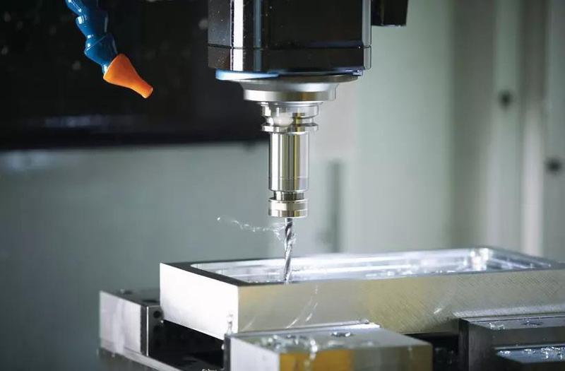
Recommended drilling sequence:
- Position the drill accurately over the hole center.
- Use a spot drill where necessary to establish the entry point.
- Apply an appropriate cutting fluid or coolant.
- Drill using a suitable spindle speed and feed rate.
- Use peck drilling when chip evacuation becomes difficult.
- Inspect the hole diameter and remove entrance burrs before tapping.
Cutting speed can be estimated using:
[ N=\frac{1000V_c}{\pi D} ]
Where:
- (N) = spindle speed (RPM)
- (V_c) = cutting speed (m/min)
- (D) = drill diameter (mm)
Practical example:
Suppose a machinist is drilling a 6.8 mm hole in aluminum using a recommended starting cutting speed of 100 m/min.
[ N=\frac{1000\times100}{3.14\times6.8} \approx4680\text{ RPM} ]
This gives an approximate spindle speed of 4,680 RPM. The actual cutting speed and feed rate should be adjusted according to the drill manufacturer’s recommendations, machine rigidity, tool diameter, coolant delivery, and workpiece conditions.
For deep holes, peck drilling can help break and evacuate chips. However, excessive pecking can increase cycle time and cause unnecessary tool wear. Continuous drilling may be preferable when the tool geometry and chip evacuation conditions allow it.
7. Choosing the Right Tapping Method and Cutting Parameters
After drilling, the hole is ready for tapping. The correct tapping method depends on the machine, material, thread size, production volume, and hole geometry.
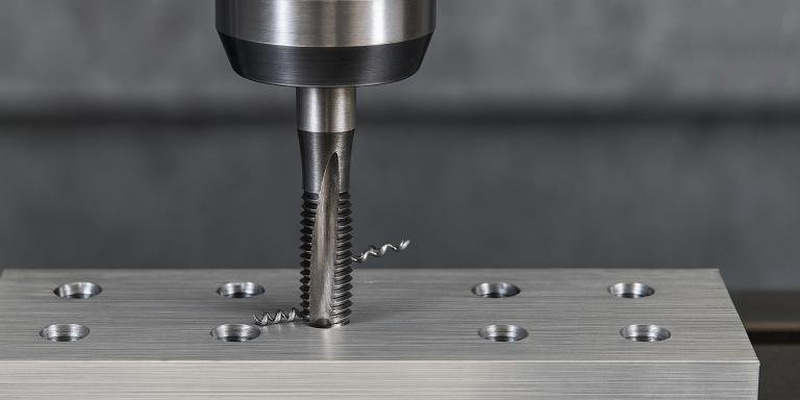
There are three common tapping methods:
Hand tapping
Hand tapping is generally used for maintenance, repairs, prototypes, and low-volume production. The machinist manually rotates the tap using a tap wrench while maintaining alignment with the hole.
Machine tapping
Machine tapping uses a drilling machine, milling machine, or CNC machine to control the tapping operation. It improves repeatability and is suitable for production environments.
CNC rigid tapping
Rigid tapping synchronizes spindle rotation with the Z-axis feed. The spindle advances by exactly one thread pitch per revolution, helping produce consistent thread geometry.
For example, an M8 × 1.25 tap requires an axial feed of 1.25 mm per spindle revolution. At 500 RPM:
[ F=500\times1.25=625\text{ mm/min} ]
The programmed tapping feed is therefore 625 mm/min, assuming the machine uses millimeters and the tapping cycle is configured correctly.
Typical starting considerations by material
| Material | Tapping considerations |
|---|---|
| Aluminum 6061 | Sharp taps, effective lubrication, good chip evacuation |
| Stainless steel 304 | Avoid rubbing, control heat, use suitable cutting fluid |
| Mild steel | Match tap geometry and cutting speed to material hardness |
| Brass | Use appropriate tap geometry to prevent grabbing |
| Titanium | Control heat, maintain tool rigidity, use manufacturer-approved parameters |
These are process considerations rather than universal speed settings. Tap diameter, coating, flute design, material condition, and machine capability all influence the final parameters.
For CNC production, rigid tapping is especially useful when a component contains multiple threaded holes that must maintain consistent depth and quality.
8. Understanding Blind Holes Versus Through Holes
The distinction between blind holes and through holes directly affects tap selection, drilling depth, and chip evacuation.
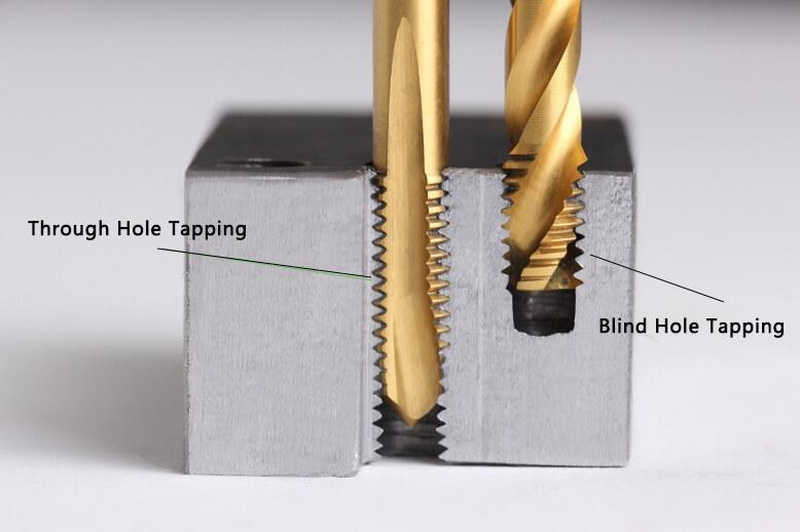
Through holes extend completely through the workpiece. They generally provide better chip evacuation because chips can move through the opposite end of the hole.
Spiral-point taps are often suitable for through-hole applications because they push chips forward. This reduces the risk of chips accumulating in front of the cutting edges.
Blind holes stop inside the workpiece and have a closed bottom. They are more challenging because chips must be removed through the hole entrance, and the tap must avoid contacting the bottom.
Spiral-flute taps are frequently used for blind holes because they help pull chips upward. The machinist must also account for the drill-point depth and the tap’s chamfer length.
Consider an aluminum housing requiring an M6 × 1 threaded hole with 10 mm of usable thread depth. The drilled hole must be deeper than 10 mm to accommodate the tap lead and drill-point geometry. The exact additional depth depends on the tap design and required bottom clearance.
Never assume that the programmed tap depth equals the finished usable thread depth. Verify the tool geometry and drawing requirements before machining.
9. Avoiding Common Drilling and Tapping Problems
Even when the correct tools are selected, several machining problems can affect thread quality.
| Common problem | Possible cause | Recommended solution |
|---|---|---|
| Broken tap | Small pilot hole or excessive torque | Verify drill size and reduce tapping load |
| Damaged threads | Worn tap or poor alignment | Replace tooling and check spindle alignment |
| Oversized hole | Drill runout or excessive wear | Inspect tool condition and spindle runout |
| Rough threads | Incorrect cutting speed or lubrication | Optimize parameters and coolant |
| Chip blockage | Poor chip evacuation | Select suitable flute geometry |
| Tapping too deep | Incorrect depth programming | Check usable thread depth and bottom clearance |
| Misaligned threads | Poor workholding or positioning | Improve fixturing and coordinate accuracy |
One particularly serious issue is work hardening when machining stainless steel. If the cutting edge rubs instead of cutting effectively, the material surface can become harder, increasing tapping torque and the risk of tool failure.
For this reason, machinists should use sharp tools, avoid unnecessary dwell, maintain suitable feed conditions, and ensure adequate lubrication.
Another frequent issue is using the same tapping strategy for every material. Aluminum, stainless steel, brass, and titanium have different cutting characteristics. A process that works well for aluminum may produce poor results in stainless steel.
10. Measuring and Inspecting Finished Threaded Holes
Drilling and tapping are not complete until the finished thread has been inspected.
A threaded hole may look acceptable visually but still fail during assembly because of incorrect pitch, insufficient thread depth, excessive thread clearance, or damaged thread flanks.
Common inspection tools include:
- GO/NO-GO thread plug gauges: Check whether an internal thread meets the specified acceptance limits.
- Calipers: Measure accessible hole diameters and general component dimensions, but do not replace thread gauges.
- Depth gauges: Verify the depth of the drilled hole and usable thread.
- Coordinate Measuring Machines (CMMs): Inspect hole location, orientation, and dimensional relationships.
- Optical inspection systems: Help identify visible burrs, surface damage, and machining defects.
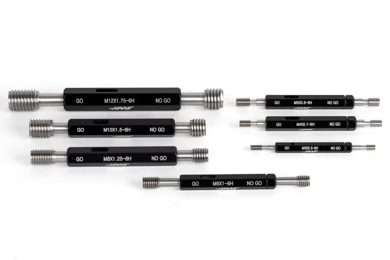
For example, if an engineering drawing specifies M8 × 1.25-6H, the finished hole should be inspected using the appropriate metric thread plug gauge. The GO gauge should enter within the applicable inspection requirements, while the NO-GO gauge should not exceed the acceptance limit specified by the governing thread standard.
For high-precision components, inspection should also consider hole position, perpendicularity, thread depth, and the relationship between threaded holes and mating components.
A good inspection process reduces assembly failures and helps ensure that CNC-machined parts meet customer specifications.
How Xavier Ensures Accurate Drilling and Tapping in CNC Machining
Producing a high-quality threaded hole requires more than selecting the correct drill bit and tap. It involves coordinated control of material selection, machining parameters, tooling, workholding, thread specifications, and inspection procedures.
At Xavier, we provide professional CNC machining services for international B2B customers, specializing in custom metal parts and precision-machined components. Our manufacturing capabilities support drilling, tapping, CNC milling, CNC turning, and secondary machining operations for a wide range of engineering materials.
Whether your project requires M3 mounting holes in aluminum brackets, M8 threaded holes in stainless steel housings, or precision internal threads in complex industrial components, selecting the correct machining process is essential to achieving reliable assembly performance.
We focus on the following aspects:
- Thread accuracy: Following engineering drawings and specified thread standards.
- Material-specific machining: Adjusting drilling and tapping strategies for aluminum, stainless steel, brass, titanium, and alloy steel.
- Consistent production quality: Controlling hole positioning, thread depth, and dimensional tolerances.
- Quality inspection: Using appropriate measuring equipment and thread gauges to verify finished components.
- Custom manufacturing: Supporting prototypes, low-volume orders, and larger production requirements.
If you are looking for a reliable CNC machining manufacturer for custom threaded components, contact Xavier. Send us your 2D drawings or 3D CAD files to discuss your material requirements, thread specifications, machining options, and quotation.
Xavier – Your Reliable Partner for Custom CNC Machining and Precision Metal Parts Manufacturing.
As an integrated CNC machining manufacturer and trading company, Xavier specializes in custom CNC machining services and the production of precision metal components. We also offer a range of professional surface finishing solutions, including CNC anodizing surface finishing, CNC zinc electroplating surface finishing, and CNC passivation surface finishing.
We are a reliable CNC anodizing manufacturer, providing bulk CNC zinc electroplating services and competitive CNC passivation pricing. Feel free to contact us to discuss your project requirements and get a customized quotation.
Some of the images and text in this article are collected and compiled from the internet. If there is anything inappropriate, please contact us for processing.