
Drone Prototype to Mass Production CNC: A Complete Manufacturing Guide
Moving a drone component from prototype to mass production requires more than increasing the number of parts machined. UAV manufacturers must validate the design, select the right materials, control critical dimensions, optimize machining time, and establish a repeatable quality inspection process. A motor mount that works on one prototype may still develop alignment problems in a production batch if its machining datums, tolerances, or workholding method are not properly controlled.
CNC machining provides a practical manufacturing route for custom drone frames, motor mounts, gimbal brackets, payload supports, sensor housings, and other precision UAV components. It allows engineers to revise designs without investing in dedicated production molds, while supporting the transition from individual prototypes to repeat orders.
The following guide covers 10 essential topics for drone manufacturers, product development teams, and purchasing engineers planning to scale CNC-machined UAV parts.
10 Key Topics to Cover
- Drone prototype development and functional validation
- Material selection for lightweight, strong UAV components
- Design for manufacturability (DFM) and cost reduction
- CNC machining processes and multi-axis manufacturing
- Dimensional tolerances and geometric control
- Lightweight design and structural optimization
- Surface finishing and corrosion protection
- Pilot runs, production fixtures, and process repeatability
- Quality inspection and production traceability
- Production cost, lead time, and CNC supplier selection
1. Drone Prototype Development and Functional Validation
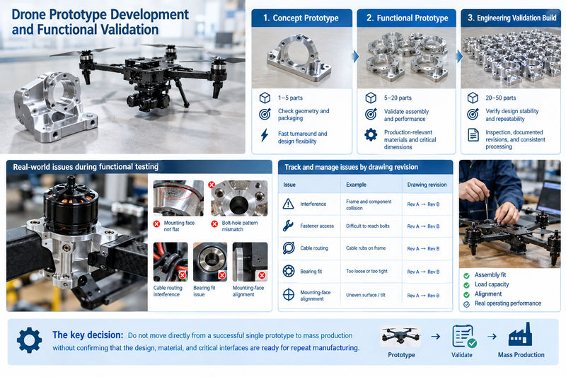
A CNC-machined drone prototype should answer specific engineering questions before a manufacturer commits to a larger production order. The purpose is not simply to confirm that a part matches the CAD model. It is to determine whether the component can be assembled correctly, withstand its expected loads, maintain alignment, and perform under realistic operating conditions.
For example, a custom UAV motor mount may look correct on a drawing but still cause problems when installed. If the mounting face is not sufficiently flat, or the bolt-hole pattern does not match the motor base, tightening the fasteners can introduce unwanted stress or misalignment. During operation, this may contribute to vibration, uneven loading, or premature wear.
Three stages of drone prototyping
| Development stage | Typical quantity (illustrative) | Main objective | Manufacturing priority |
|---|---|---|---|
| Concept prototype | 1–5 parts | Check geometry and packaging | Fast turnaround and design flexibility |
| Functional prototype | 5–20 parts | Validate assembly and performance | Production-relevant materials and critical dimensions |
| Engineering validation build | 20–50 parts | Verify design stability and repeatability | Inspection, documented revisions, and consistent processing |
These quantities are planning examples, not fixed industry standards. A complex drone program may require more iterations, while a simple bracket may need only a few samples.
During functional testing, engineers should record problems such as interference between components, fastener access, cable routing, bearing fit, and mounting-face alignment. Each issue should be linked to a specific drawing revision. If the motor mount is revised from Rev A to Rev B, the supplier and engineering team must know which version was tested and which version is approved.
The key decision: Do not move directly from a successful single prototype to mass production without confirming that the design, material, and critical interfaces are ready for repeat manufacturing.
2. Material Selection for Lightweight, Strong UAV Components
Material selection affects drone weight, structural stiffness, machining cost, corrosion resistance, and component life. The correct material depends on the part’s function rather than the assumption that the strongest available alloy is always the best choice.
Comparing common CNC materials for drone parts
| Material | Approx. density (g/cm³) | Main advantages | Typical applications |
|---|---|---|---|
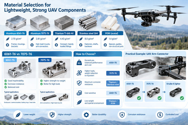
| Aluminum 6061-T6 | 2.70 | Good machinability, corrosion resistance, balanced cost | Frames, housings, brackets, heat sinks |
| Aluminum 7075-T6 | 2.81 | High strength-to-weight performance | Highly loaded mounts, arm connectors |
| Titanium alloy Ti-6Al-4V | 4.43 | High specific strength and corrosion resistance | Compact, heavily loaded fittings |
| Stainless steel 304 | 8.0 | Corrosion resistance and general-purpose durability | Fasteners, shafts, selected hardware |
| POM (acetal) | 1.4 | Low friction, good machinability, electrical insulation | Spacers, guides, non-structural components |
Density values are approximate; actual properties depend on grade and material condition.
When should you choose 6061-T6 or 7075-T6?
6061-T6 is a practical starting point for many CNC drone components because it machines efficiently and offers a useful balance of strength, corrosion resistance, and price. It is suitable for electronics housings, camera brackets, battery trays, and many structural connectors.
7075-T6 is worth considering when a component experiences higher mechanical loads and weight reduction is important. However, it generally costs more and requires greater attention to corrosion protection and finishing. Replacing every 6061 part with 7075 can increase costs without producing a meaningful performance improvement.
Titanium is more appropriate when its particular mechanical or environmental advantages justify the higher raw-material and machining costs. It is not automatically the best choice for lightweight drone construction because titanium is considerably denser than aluminum.
A practical example is a UAV arm connector. If 6061-T6 already satisfies the load requirements with an adequate safety margin, changing to 7075-T6 may offer limited benefit. If the connector must become smaller while maintaining its required load capacity, 7075 may be more attractive.
3. Design for Manufacturability (DFM) and CNC Cost Reduction
Design for manufacturability should begin before the first prototype is machined. A part can be technically manufacturable but still be unnecessarily expensive because its geometry requires tiny cutting tools, deep pockets, multiple setups, or extensive manual finishing.
Geometry that increases machining time
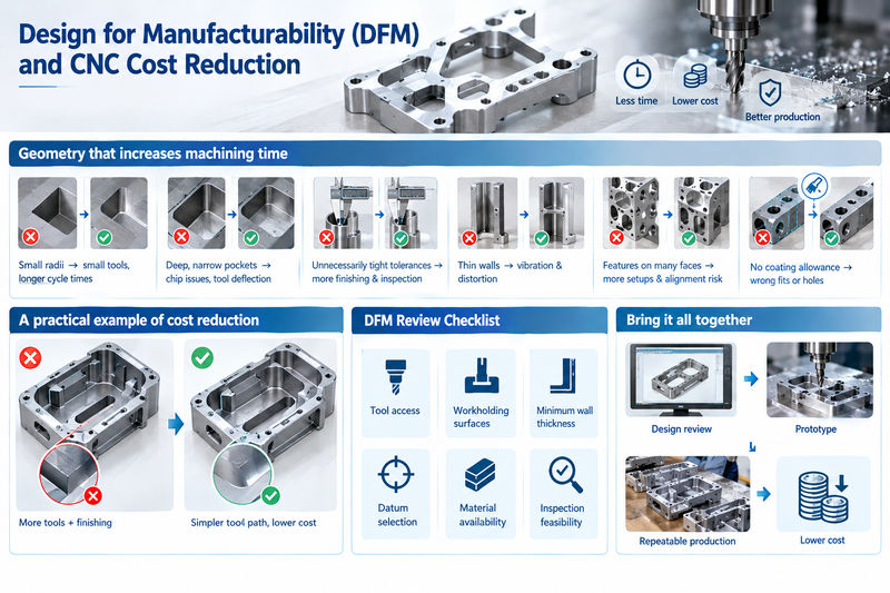
Consider an aluminum drone frame bracket with several deep pockets and sharp internal corners. If the corner radius is smaller than the available standard cutting tool can produce, the machinist may need a smaller end mill. Smaller tools are generally less rigid, may require reduced cutting parameters, and can increase machining time.
A more production-friendly design may use larger internal radii wherever the assembly allows them. Similarly, shallow pockets with accessible tool paths are often easier to manufacture than deep, narrow cavities with the same material-removal volume.
| Design issue | Manufacturing consequence | Practical improvement |
|---|---|---|
| Extremely small internal radii | Small tools and longer cycle times | Increase radii where functional requirements permit |
| Deep, narrow pockets | Difficult chip evacuation and tool deflection | Reduce depth or widen access |
| Unnecessarily tight tolerances | More finishing operations and inspection | Tighten only function-critical dimensions |
| Very thin unsupported walls | Vibration and dimensional distortion | Add ribs or improve workholding |
| Features on many different faces | More setups and alignment risk | Consolidate accessible features |
| Unspecified coating allowance | Final holes or fits may be incorrect | Define finishing and dimensional requirements together |
A practical example of cost reduction
Suppose a prototype housing contains four narrow internal slots that do not contact any mating component. If the design requires exceptionally small corner radii, machining may involve several tools and additional finishing passes. Increasing the radii could simplify the tool path without affecting the housing’s function.
The savings will depend on geometry, batch size, machine availability, and tooling. Therefore, a supplier should explain the proposed change and obtain engineering approval rather than modify the customer’s design without authorization.
A useful DFM review should cover tool access, workholding surfaces, minimum wall thickness, datum selection, material availability, and inspection feasibility. These decisions help determine whether a design that works once can also be produced efficiently in repeat batches.
4. CNC Milling, Turning, and Multi-Axis Manufacturing
Not every drone component needs the same machining process. Choosing the appropriate process for each geometry can reduce setup time, improve feature relationships, and avoid unnecessary production costs.
Which CNC process suits each component?
| Manufacturing process | Best suited to | Example drone components |
|---|---|---|
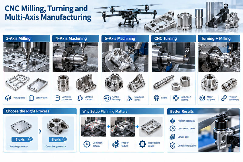
| 3-axis CNC milling | Plates, pockets, flat surfaces, standard brackets | Frame plates, battery trays |
| 4-axis CNC machining | Parts requiring indexed or continuous rotational access | Cylindrical connectors, selected complex brackets |
| 5-axis CNC machining | Multiple angled surfaces and complex three-dimensional geometry | Gimbal housings, intricate structural joints |
| CNC turning | Rotationally symmetric features | Shafts, bushings, spacers, adapters |
| CNC turning and milling combination | Parts combining cylindrical and milled features | Motor adapters, precision connectors |
A conventional 3-axis machine is often sufficient for a motor mounting plate with a straightforward hole pattern and pocketed geometry. Choosing a 5-axis machine for that part may not offer enough benefit to justify the additional cost.
By contrast, a gimbal housing with angled bearing seats and mounting features on several faces may benefit from 5-axis machining. Fewer setups can reduce accumulated repositioning errors and help maintain the relationship between critical features.
Why setup planning matters
Every time a component is removed, repositioned, and clamped again, a new opportunity for alignment error is introduced. A carefully planned fixture and machining sequence can keep important surfaces and holes related to a common datum.
For production orders, the supplier should establish a repeatable machining route instead of improvising the setup for each part. This is especially important when manufacturing motor mounts, propeller adapters, and sensor interfaces where geometric relationships directly affect assembly.
5. Dimensional Tolerances and Geometric Control
Dimensional accuracy is essential for drone components, but applying extremely tight tolerances to every feature is rarely the most economical approach. Engineers should identify which dimensions control assembly, alignment, rotation, sealing, or structural performance and specify tolerances accordingly.
Typical tolerance planning for CNC drone parts
The following values are illustrative starting points for engineering discussions, not universal acceptance limits. Actual requirements depend on the drawing, material, geometry, machine capability, inspection method, and operating conditions.
| Feature | Illustrative tolerance target | Engineering reason |
|---|---|---|
| General housing dimensions | ±0.10 mm | Overall fit and packaging |
| Frame connection holes | ±0.05 mm | Assembly alignment |
| Motor mounting features | ±0.02 mm | Motor positioning |
| Precision bearing seat | ±0.01 mm | Bearing fit and operation |
| Mounting-face flatness | 0.02 mm | Contact and alignment |
A bearing seat may require tighter control than an external housing dimension because excessive clearance can affect support and excessive interference can create unwanted assembly stress. The correct fit must be selected using the bearing specification, loading conditions, and operating temperature.
Understand tolerance stack-up
Suppose a drone motor is mounted to an arm connector, which is attached to a central frame. Even if each individual part meets its own dimensional tolerances, the combined positional variation may cause the motor to sit outside the intended alignment.
Geometric dimensioning and tolerancing (GD&T) helps control relationships between features through datums, position tolerances, flatness, perpendicularity, and other geometric requirements. For a production-ready drawing, identifying a reliable datum structure is often more useful than assigning an arbitrary ±0.01 mm tolerance to every dimension.
Manufacturers should also consider post-machining operations. An anodized hole, for example, may have a different final diameter from the same hole before coating. Critical bearing seats, threaded holes, and electrical contact surfaces may require masking or a specifically planned finishing sequence.
6. Lightweight Design and Thin-Wall CNC Machining
Reducing drone weight can improve payload capacity or flight endurance, but excessive material removal can weaken the structure or make machining less stable. The objective is to maximize stiffness and strength relative to weight, not simply to remove as much aluminum as possible.
How to remove material without sacrificing stiffness
CNC milling can create pockets, ribs, relief channels, and locally reinforced mounting areas. These features allow engineers to remove material from lower-stress regions while retaining more material around fasteners, load paths, and interfaces.
Consider a 7075-T6 drone arm connector. Deep pockets may reduce its mass, but if they leave long, unsupported walls, cutting forces can cause vibration and deformation. The part may appear dimensionally correct while clamped and then spring out of shape after unclamping.
A more reliable machining strategy may include:
- Retaining adequate material around bolt holes and highly loaded corners.
- Using ribs to improve stiffness without restoring unnecessary bulk.
- Removing material symmetrically where practical to reduce distortion.
- Rough-machining first, allowing stress or distortion to be assessed, then finish-machining critical surfaces.
- Using appropriate workholding to support thin sections during cutting.
There is no single minimum wall thickness suitable for every drone component. A 1 mm wall may be workable in one short, well-supported feature and unsuitable in a long, unsupported section with tight flatness requirements.
Example: Optimizing a camera bracket
A camera bracket must be light, but it must also resist deflection that could affect image stability. Instead of thinning the entire bracket uniformly, the engineer can retain material around mounting holes and bearing interfaces while pocketing less critical regions.
The final design should be evaluated for stiffness, vibration behavior, mounting loads, and manufacturability. A lighter prototype is not automatically a better production component if it becomes more expensive to machine or less reliable in service.
7. Surface Finishing and Corrosion Protection
Surface finishing affects durability, wear, appearance, and dimensional fit. A drone component exposed to rain, humidity, dust, or repeated handling may need a different finish from an internal component protected inside an electronics enclosure.
Selecting a suitable surface finish
| Finish | Primary purpose | Typical applications |
|---|---|---|
| Type II anodizing | Corrosion protection and appearance | Aluminum frames, brackets, housings |
| Type III hard anodizing | Increased surface wear resistance | Selected wear-prone aluminum interfaces |
| Bead blasting | Uniform matte texture | Visible housings and brackets |
| Passivation | Improve corrosion resistance of suitable stainless steel | Stainless steel fittings |
| Electroless nickel plating | Surface protection and wear-related performance | Selected precision mechanical parts |
The appropriate treatment depends on the substrate, environment, and performance requirements. For example, Type III hard anodizing may suit an aluminum component exposed to repeated contact, but it is not automatically necessary for every drone bracket.
Why finishing must be planned before machining
Coating thickness can affect the final dimensions of holes, slots, mating faces, and bearing seats. If a motor adapter requires a specific fit, the supplier must consider the finishing allowance before the final machining operation.
Masking may be necessary where electrical contact, grounding, or precise mechanical contact must be maintained. Threads may also require protection or post-treatment verification, depending on the coating and drawing.
For mass production, the finishing specification should identify the process, required appearance or performance, masked areas, and inspection criteria. Simply specifying “black anodizing” may not be enough to ensure consistent results across different batches.
8. Pilot Runs, Production Fixtures, and Repeatability
A successful prototype demonstrates that a part can work. A pilot run determines whether the manufacturing process can reproduce that part consistently.
Before releasing a large order, manufacturers should establish a stable machining program, approved material specification, workholding method, tool strategy, and inspection procedure. A pilot run can reveal issues that may not appear when producing only one or two components.
A practical scale-up plan
| Stage | Main activity | Release decision |
|---|---|---|
| Prototype | Produce initial parts and test assembly | Is the design functional? |
| Design freeze | Approve CAD and drawing revisions | Is the design ready for controlled production? |
| Pilot run | Produce a representative small batch | Are dimensions and processes repeatable? |
| Production release | Approve inspection and manufacturing documentation | Can the batch be produced to the agreed requirements? |
| Repeat production | Monitor quality, tooling, and delivery | Are results remaining consistent? |
The quantities and timing for each stage should be agreed according to project complexity and risk.
Why fixtures and tool management matter
A well-designed fixture locates the component consistently and supports it against cutting forces. For repeated batches, dedicated or standardized fixtures can reduce setup variation and improve cycle-time predictability.
Tool wear must also be considered. A cutting tool that produces acceptable dimensions at the beginning of a batch may gradually affect surface finish or dimensional accuracy as it wears. Production planning should establish suitable tool-life checks, inspection intervals, and replacement criteria.
Design changes require similar discipline. If a pilot run identifies a weak mounting feature, the revised drawing must be formally approved and the previous version clearly identified. Otherwise, old and new components may become mixed in the same production batch.
9. Quality Inspection and Production Traceability
For CNC-machined UAV components, quality control should verify functional requirements rather than rely only on visual inspection. A component can have an excellent surface finish and still fail because its bearing seat, mounting-hole pattern, or datum relationship is incorrect.
Inspection methods for drone components
| Inspection method | What it verifies | Typical application |
|---|---|---|
| Calipers and micrometers | Basic dimensions and thickness | Plates, spacers, general features |
| Pin gauges and bore gauges | Hole sizes and internal diameters | Mounting holes, bearing seats |
| Coordinate measuring machine (CMM) | Complex dimensions and geometric relationships | Gimbal brackets, precision housings |
| Surface roughness tester | Surface texture | Bearing and mating surfaces |
| Visual inspection | Burrs, scratches, finish defects | All finished components |
For an initial production batch, first-article inspection can establish whether the machining process meets the drawing requirements. The report may include actual measurements, drawing references, material information, and the applicable revision.
Production inspection should then be based on the part’s risk and the customer’s requirements. Critical dimensions may require more frequent checks than non-functional external dimensions.
Traceability is also important when material properties or batch consistency matter. Material certificates, inspection records, approved drawings, and finishing documentation can help identify the source of a problem if a component fails during assembly or testing.
The required level of documentation should be agreed before ordering. A supplier should not claim aerospace qualification or certification unless it actually holds the relevant credentials and can substantiate them.
10. Production Cost, Lead Time, and CNC Supplier Selection
The cost of CNC drone parts changes as a project moves from prototypes to mass production. A prototype may carry a relatively high unit cost because programming, setup, and engineering review are spread across only a few parts. Larger batches can distribute these costs over more units, but the unit price does not necessarily decrease in a straight line.
What determines the total manufacturing cost?
| Cost factor | Effect on production |
|---|---|
| Material grade and stock size | Influences raw-material cost and waste |
| Part geometry | Determines machining complexity |
| Number of setups | Affects setup labor and alignment risk |
| Tight tolerances | May require additional finishing and inspection |
| Surface treatment | Adds processing time and cost |
| Batch quantity | Changes how setup costs are distributed |
| Inspection documentation | Adds measurement and reporting work |
| Packaging and delivery | Affect the final landed cost |
A part machined from a large billet may generate substantial waste if its final geometry contains deep pockets. Adjusting the blank size or simplifying non-functional features can reduce cost, provided the required material properties and structural performance remain acceptable.
Lead time should also be evaluated across the complete process. The machining cycle may take only a few hours, while material procurement, programming, finishing, inspection, and international shipping may account for much of the overall schedule.
How to evaluate a CNC manufacturing supplier
A suitable supplier should be able to explain how it will manufacture the part, control its critical dimensions, manage finishing requirements, and reproduce the approved design in subsequent batches.
Before requesting a quotation, prepare the following information:
- A current 3D CAD model and dimensioned 2D drawing.
- Material grade and heat-treatment condition, where applicable.
- Prototype quantity and expected production volumes.
- Critical dimensions and GD&T requirements.
- Surface finish, anodizing, plating, or masking requirements.
- Inspection reports, material certificates, or other documentation required.
- Target delivery date, packaging, and shipping requirements.
Ask the supplier to quote the prototype and expected production quantities separately. This makes it easier to compare setup costs, unit prices, tooling assumptions, and inspection requirements without assuming that a prototype quotation will remain valid for mass production.
The right manufacturing partner is one that helps establish a controlled process from the first sample through repeat production, rather than simply offering the lowest initial unit price.
Why Choose Xavier for Drone Prototype to Mass Production CNC?
Moving a drone design from prototype to mass production requires a manufacturing partner who understands the relationship between material selection, machining strategy, dimensional accuracy, and production consistency.
Xavier provides custom CNC machining services for drone and UAV components, including aluminum brackets, motor mounts, structural connectors, gimbal components, precision housings, and other custom metal parts. Our manufacturing approach supports projects requiring prototype development, design refinement, and repeat production.
Whether you are developing a new UAV platform or scaling an existing design, our team can review your drawings, assess machining feasibility, and identify practical opportunities to optimize cost without compromising specified functional requirements.
Ready to move your drone project from prototype to production?
Send Xavier your 3D CAD files, 2D engineering drawings, material requirements, and estimated order quantities. We can review your requirements and help you develop a practical CNC manufacturing solution for your next UAV production run.
Visit CNC Machining Services to discuss your project and request a quotation.
As an integrated CNC manufacturing and trading company, we specialize in custom CNC machining and contract manufacturing of metal components for global customers. Our capabilities cover a broad range of metals, alloys, and engineering plastics, supporting applications in robotics, aerospace, marine engineering, automotive manufacturing, medical equipment, and other precision industries. We provide CNC machining of PEEK, CNC milling services, and CNC machining of stainless steel, along with custom manufacturing solutions for alloy steel, aluminum, brass, bronze, copper, Inconel, Invar 36, mild steel, titanium, tool steel, ABS, FR4, G-10, nylon, PEI, PET, PMMA (acrylic), polycarbonate, polyethylene, polypropylene, POM (acetal), PPSU, PTFE, and PVC. Whether you need prototypes, small batches, or large-volume production, we work to meet your component specifications and manufacturing requirements.
We are a reliable CNC machining of PEEK manufacturer, offering high-volume CNC milling services and competitive CNC machining of stainless steel pricing. Contact us to discuss your project requirements and obtain a customized quotation.
Some of the images and text in this article are collected and compiled from the internet. If there is anything inappropriate, please contact us for processing.