
Anodized Aluminum Drone Brackets: Materials, CNC Machining, Design, and Quality Control
Anodized aluminum drone brackets may look like simple mounting components, but their performance depends on much more than material strength or surface appearance. A bracket connecting a drone motor, landing gear, camera gimbal, flight controller, or payload assembly must maintain alignment under vibration, repeated acceleration, temperature changes, and mechanical loading.
From a manufacturing and procurement perspective, the critical question is not simply whether a bracket can be machined from aluminum. It is whether the selected alloy, bracket geometry, machining tolerances, anodizing specification, and inspection plan work together in the finished assembly.
For most custom UAV applications, 6061-T6 and 7075-T6 are two practical starting points. Type II anodizing is often suitable for corrosion protection and appearance, while Type III hardcoat anodizing is worth considering for wear-prone interfaces. The correct choice depends on the actual load, environment, dimensional requirements, and service life.
The following five engineering topics explain how to specify and manufacture anodized aluminum drone brackets without introducing unnecessary weight, cost, or assembly problems.
1. Aluminum Alloy Selection for Drone Brackets: 6061-T6 vs. 7075-T6
Material selection directly affects bracket stiffness, fatigue performance, machinability, corrosion behavior, and total manufacturing cost. Choosing the strongest available alloy is not always the best decision. A bracket carrying a lightweight camera may have different requirements from a motor mount exposed to sustained vibration and high thrust loads.
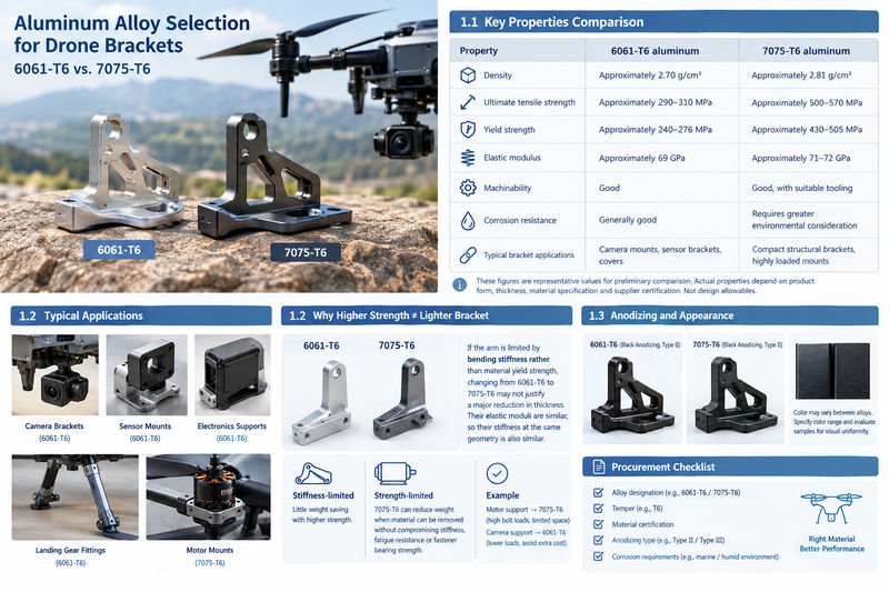
1.1 Comparing 6061-T6 and 7075-T6
6061-T6 offers a useful balance of strength, machinability, corrosion resistance, and finishing flexibility. It is commonly considered for camera brackets, sensor mounts, electronics supports, landing gear fittings, and general-purpose UAV structural components.
7075-T6 provides substantially higher tensile strength and is attractive for compact structural brackets where space and weight are limited. However, its corrosion behavior and stress-corrosion considerations require more attention, particularly in marine, coastal, or humid environments.
The following figures are representative engineering values for preliminary comparison. Actual properties depend on product form, thickness, material specification, and supplier certification.
| Property | 6061-T6 aluminum | 7075-T6 aluminum |
|---|---|---|
| Density | Approximately 2.70 g/cm³ | Approximately 2.81 g/cm³ |
| Ultimate tensile strength | Approximately 290–310 MPa | Approximately 500–570 MPa |
| Yield strength | Approximately 240–276 MPa | Approximately 430–505 MPa |
| Elastic modulus | Approximately 69 GPa | Approximately 71–72 GPa |
| General machinability | Good | Good, with suitable tooling |
| Corrosion resistance | Generally good | Requires greater environmental consideration |
| Typical bracket applications | Camera mounts, sensor brackets, covers | Compact structural brackets, highly loaded mounts |
These figures are not design allowables. For flight-critical components, engineers should use certified material data applicable to the actual stock form, thickness, loading direction, and governing design standard.
1.2 Why higher strength does not automatically mean a lighter bracket
Consider a bracket with a narrow mounting arm and two bolt holes. If the arm is limited by bending stiffness rather than material yield strength, changing from 6061-T6 to 7075-T6 may not justify a major reduction in thickness. Their elastic moduli are similar, so their stiffness at the same geometry is also similar.
7075-T6 becomes more attractive when the design is strength-limited and material can be removed without compromising stiffness, fatigue resistance, local buckling resistance, or fastener bearing strength.
For example, a compact motor support may benefit from 7075-T6 if the bracket experiences high bolt loads and limited mounting space. A camera support operating under lower loads may achieve the required performance with 6061-T6, avoiding unnecessary material and qualification costs.
1.3 Match the alloy to the anodizing process
Both alloys can be anodized, but their final appearance and coating behavior may differ. Alloy composition, surface preparation, and process control affect color consistency, particularly when different alloys are used in the same assembly.
A black Type II finish on a 6061 bracket may not match a black finish on a 7075 component perfectly. If visual uniformity matters, specify an acceptable color range and evaluate production samples rather than assuming all black anodized aluminum will look identical.
For procurement, request the alloy designation, temper, material certification, anodizing type, and any relevant corrosion requirements before approving the first production batch.
2. Type II vs. Type III Anodizing: Choosing the Right Surface Finish
Anodizing is an electrochemical process that forms a controlled aluminum oxide layer on the surface. Unlike paint, the oxide is produced from the aluminum itself. It improves surface protection and can provide a decorative finish, but it also changes the dimensions of machined features.
For drone brackets, the correct anodizing specification depends on the function of the surface, not simply its color.
2.1 Type II anodizing for general-purpose drone brackets
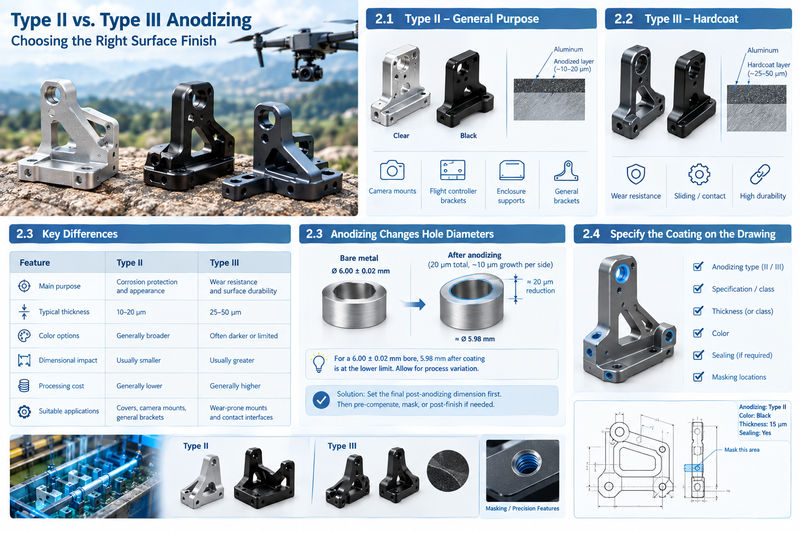
Type II sulfuric acid anodizing is suitable for many brackets that require corrosion protection, a consistent appearance, and moderate surface durability. Clear and black finishes are common, while other colors may be available depending on the alloy and process.
Typical applications include camera mounting plates, flight-controller brackets, electronic enclosure supports, and external mounting components.
A nominal coating thickness around 10–20 μm is a useful preliminary reference for many Type II applications, but the actual requirement must be established by the applicable drawing or specification. Coating thickness, dye selection, sealing, and corrosion performance should be agreed upon with the finishing supplier.
2.2 Type III hardcoat for wear-prone interfaces
Type III hardcoat anodizing generally produces a thicker, harder oxide layer than Type II. It is worth considering for brackets that experience repeated assembly, sliding contact, abrasion, or wear around locating interfaces.
A typical engineering reference range is approximately 25–50 μm, although the required thickness depends on the applicable specification and intended service conditions.
Hardcoat is not automatically superior for every drone bracket. It may increase finishing cost, create greater dimensional changes, complicate color matching, and introduce additional concerns for fatigue-sensitive edges or highly stressed surfaces.
| Comparison | Type II anodizing | Type III hardcoat |
|---|---|---|
| Main purpose | Corrosion protection and appearance | Wear resistance and surface durability |
| Typical reference thickness | 10–20 μm | 25–50 μm |
| Color options | Generally broader | Often darker or more restricted |
| Dimensional impact | Usually smaller | Usually greater |
| Processing cost | Generally lower | Generally higher |
| Suitable applications | Covers, camera mounts, general brackets | Wear-prone mounts and contact interfaces |
These thickness ranges are indicative, not universal acceptance limits. The drawing and governing process specification take precedence.
2.3 How anodizing changes hole diameters and mounting fits
One of the most common mistakes in manufacturing anodized aluminum drone brackets is machining every feature to its final bare-metal dimension and applying the coating afterward without accounting for growth.
As a simplified illustration, assume a coating has a total thickness of 20 μm and approximately half of that thickness contributes to outward growth on a surface. The resulting outward dimensional growth is approximately 10 μm per coated surface.
For a cylindrical bore coated on both sides, the diameter can decrease by approximately 20 μm under this simplified model. Actual changes vary with alloy, pretreatment, coating conditions, geometry, and specification.
Consider a mounting bore that must finish at 6.00 ± 0.02 mm. If the coating reduces the bore by 0.02 mm, a bore measuring 5.98 mm after finishing would be at the lower tolerance limit. Additional process variation could push it out of specification.
The solution is to establish the required final, post-anodizing dimension first. The machinist can then determine whether to pre-compensate the bore, mask it, or perform a controlled post-finish operation.
2.4 Specify the coating before releasing the drawing
A useful drawing note should identify the anodizing type, applicable specification, required thickness or class, color, sealing requirements where applicable, and masking locations.
Do not rely on a note that says only “black anodized.” That description does not fully define coating performance or dimensional requirements.
For brackets with precision bores, threaded holes, electrical grounding points, or close-fitting interfaces, mark the critical features explicitly. This allows machining and finishing to be planned as one manufacturing process rather than two unrelated operations.
3. CNC Machining Accuracy and Structural Design of Aluminum Drone Brackets
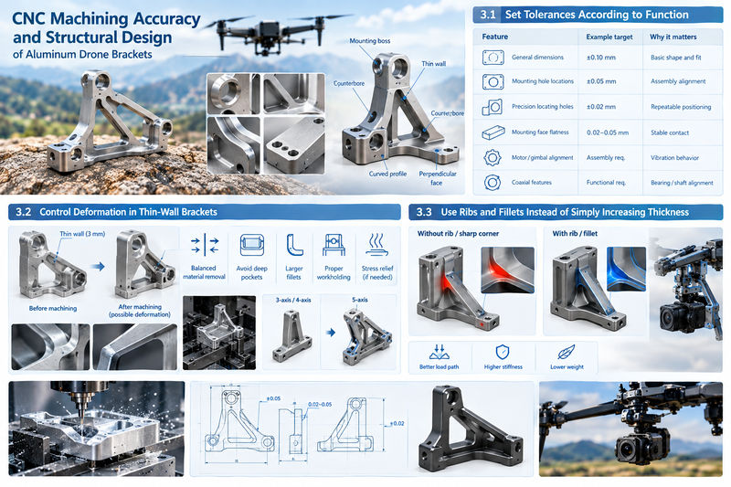
A drone bracket is rarely just a flat plate with several holes. Its geometry may include mounting bosses, thin walls, ribs, counterbores, curved profiles, and perpendicular mounting faces. These features must be machined accurately without creating unnecessary stress concentrations or excessive weight.
3.1 Set tolerances according to function
Applying extremely tight tolerances to every dimension increases machining time, inspection effort, and rejection risk. A better approach is to identify the interfaces that directly influence alignment, load transfer, and assembly.
The following are preliminary tolerance-planning examples, not guaranteed manufacturing capabilities or universal UAV requirements.
| Feature | Example drawing target | Why it matters |
|---|---|---|
| General non-critical dimensions | ±0.10 mm | Controls basic shape and fit |
| General mounting-hole locations | ±0.05 mm | Supports assembly alignment |
| Precision locating holes | ±0.02 mm | Controls repeatable positioning |
| Critical mounting-face flatness | 0.02–0.05 mm | Helps maintain stable contact |
| Motor or gimbal alignment | Defined by assembly requirements | Controls alignment and vibration behavior |
| Critical coaxial features | Set by functional analysis | Maintains bearing or shaft alignment |
A ±0.01 mm tolerance may be achievable for selected CNC-machined features under appropriate conditions, but it should not be applied indiscriminately to the entire bracket. The supplier should confirm feasibility based on part size, geometry, material, inspection method, and finishing requirements.
3.2 Control deformation in thin-wall brackets
Lightweight drone structures often contain thin sections, but thinner is not always better. When a CNC tool removes material from one side of a bracket, the remaining structure may release residual stress or deform under clamping forces.
For example, machining a deep pocket into a 3 mm thick mounting plate may reduce weight but also lower bending stiffness. If the plate distorts after unclamping, the mounting face may no longer sit flat against the drone frame.
Several manufacturing practices help reduce this risk:
- Use balanced material removal where the geometry permits.
- Avoid unnecessarily deep pockets and abrupt changes in wall thickness.
- Maintain adequate corner radii to reduce stress concentrations.
- Use suitable workholding that supports thin sections without excessive clamping force.
- Consider stress-relieved stock where material thickness and machining strategy justify it.
- Inspect critical flatness and hole positions after unclamping, not only while the part remains in the fixture.
For complex brackets, multi-axis CNC machining can reduce repeated setups and improve access to angled surfaces. However, five-axis machining is not automatically necessary; a well-planned three-axis or four-axis process may be more economical for simpler geometry.
3.3 Use ribs and fillets instead of simply increasing thickness
A bracket must resist the loads it experiences in service. Increasing thickness is one option, but ribs, curved transitions, and better load paths can sometimes deliver greater stiffness for a smaller weight penalty.
Consider a camera bracket with a long cantilevered arm. A sharp internal corner where the arm meets its mounting base can create a local stress concentration. Adding a suitable fillet and positioning a rib along the principal load path can improve structural behavior without making the entire component thicker.
The final geometry should be checked against the actual loading conditions, including payload mass, acceleration, motor vibration, landing impact, and fastener preload where relevant. For flight-critical applications, analytical calculations and appropriate testing should support the design rather than relying solely on visual judgment.
4. Weight Optimization, Vibration Resistance, and Fatigue Life
For UAV components, reducing weight can improve payload capacity or flight endurance, but the benefit depends on the complete aircraft system. A bracket that saves 8 g is not necessarily a better design if it introduces excessive vibration, poor alignment, or premature fatigue.
4.1 Calculate weight before removing material
Aluminum density is approximately 2.70–2.81 g/cm³ for the alloys discussed above. This makes material-removal estimates straightforward.
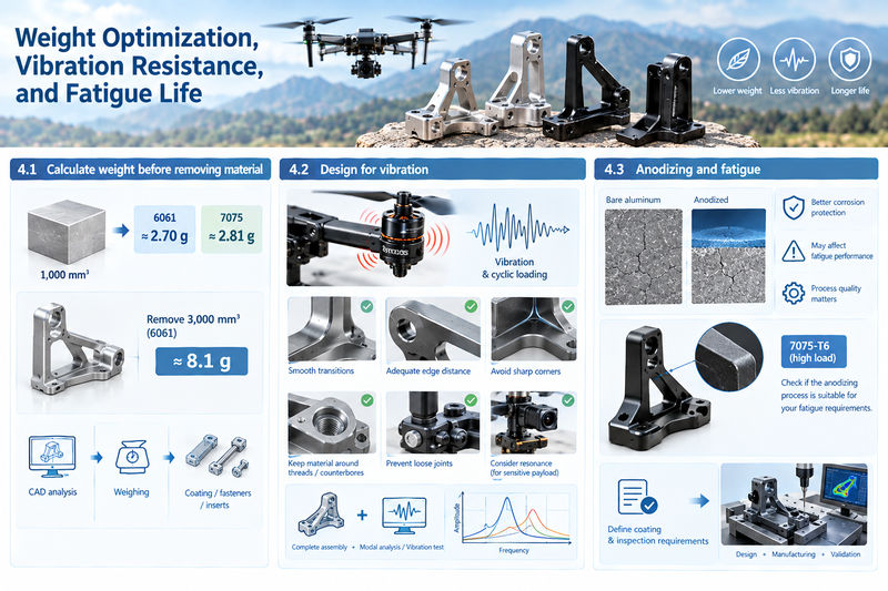
For example, removing 1,000 mm³ of aluminum corresponds to approximately:
- 2.70 g for 6061 aluminum.
- 2.81 g for 7075 aluminum.
If a bracket is redesigned to remove 3,000 mm³ of 6061 aluminum, the theoretical weight reduction is approximately 8.1 g, assuming the removed volume is accurate and no additional material is added elsewhere.
The actual mass reduction should be confirmed by CAD analysis and weighing the finished part. Coating, fasteners, inserts, and secondary features can affect the final assembly mass.
4.2 Design for vibration rather than static strength alone
Drone brackets may experience repeated loading from motors, propellers, payload mechanisms, and changes in flight direction. A component can survive a static load test and still develop fatigue cracks under cyclic loading.
Important design considerations include:
- Smooth transitions between mounting bosses and thinner arms.
- Adequate edge distance around bolt holes.
- Avoiding sharp internal corners near highly stressed regions.
- Maintaining sufficient material around threaded holes and counterbores.
- Preventing loose joints that allow repeated impact or fretting.
- Considering resonance where the bracket supports a camera, sensor, or other vibration-sensitive payload.
A stiffer bracket can reduce relative movement, but stiffness alone does not guarantee lower vibration throughout the system. The bracket interacts with the attached mass, fasteners, isolators, and supporting structure. Where vibration-sensitive equipment is involved, the complete assembly may require modal analysis or physical vibration testing.
4.3 Understand what anodizing can and cannot do for fatigue
Anodizing improves surface protection, but it should not be treated as a substitute for fatigue-resistant geometry or proper material selection. Anodic coatings can influence fatigue performance, especially on highly stressed aluminum components, because surface preparation, coating characteristics, and local defects may affect crack initiation.
For a highly loaded 7075-T6 bracket, the design engineer should consider whether the specified anodizing process is appropriate for the stress level and fatigue requirements. Critical parts may require process-specific qualification, testing, or restrictions on coating at particular surfaces.
The best manufacturing plan defines the coating and inspection requirements alongside the structural design, instead of treating anodizing as a purely cosmetic step at the end of production.
5. Quality Inspection, Manufacturing Cost, and Supplier Selection
A high-quality anodized aluminum drone bracket must meet the drawing after all manufacturing and finishing operations are complete. Measuring a bare-metal component before anodizing is not sufficient when the coating affects the critical dimensions.
5.1 Establish a practical inspection plan
Different features require different inspection methods. Calipers may be suitable for basic external dimensions, while precision bores, complex profiles, and geometric relationships may require bore gauges, pin gauges, optical measurement, or a coordinate measuring machine (CMM).
| Inspection item | Recommended verification | Main purpose |
|---|---|---|
| Material grade and temper | Material certificate and traceability | Confirms specified stock |
| Overall dimensions | Calipers, micrometers, or CMM | Verifies part size |
| Precision bores | Bore gauge or suitable calibrated gauges | Confirms fit after coating |
| Hole positions and geometric relationships | CMM or suitable fixture | Verifies assembly alignment |
| Anodizing thickness | Appropriate coating-thickness method | Checks coating requirement |
| Surface appearance | Visual inspection under defined conditions | Identifies scratches, stains, and color variation |
| Final mass | Calibrated scale | Confirms weight target |
| Critical assembly interfaces | Gauges or functional assembly checks | Confirms practical fit |
For production orders, agree on the sampling plan, first-article approval requirements, measurement records, and handling of nonconforming parts before manufacturing begins. Flight-critical programs may need more stringent controls than prototype or hobby-drone projects.
5.2 Understand the main cost drivers
The price of an anodized aluminum drone bracket is influenced by material grade, stock size, machining time, setup complexity, coating requirements, inspection effort, order quantity, and scrap risk.
A simple 6061 bracket with a few through-holes may be economical to manufacture in a single CNC setup. A compact 7075 bracket with thin walls, deep pockets, angled features, precision bores, and Type III hardcoat may require more machining time and tighter process control.
The following table illustrates the relative impact of different purchasing decisions. It is qualitative rather than a supplier quotation.
| Cost driver | Lower-cost approach | Higher-cost approach |
|---|---|---|
| Material | 6061-T6 where performance permits | 7075-T6 where higher strength is required |
| Geometry | Accessible features and uniform walls | Deep pockets, thin walls, complex multi-face geometry |
| Tolerances | Tight only on functional features | Tight tolerances across most dimensions |
| Surface treatment | Type II where sufficient | Type III with additional process controls |
| Inspection | Standard dimensional checks | CMM reports, first-article documentation, special testing |
| Order quantity | Repeat production with stable setup | One-off parts requiring dedicated programming and setup |
The lowest unit price is not always the lowest total cost. A bracket that requires rework because its bore shrinks after anodizing may consume more time and money than a slightly more expensive component produced with the correct finishing allowance.
5.3 A practical example: procuring a camera-gimbal bracket
Suppose a UAV manufacturer needs 100 aluminum brackets for a stabilized camera assembly. The bracket includes four mounting holes, a locating bore, a lightweight arm, and a black anodized exterior.
A sensible procurement process would proceed as follows.
Step 1: Define the functional requirements. Establish the camera mass, expected acceleration, mounting arrangement, allowable deflection, vibration environment, and required alignment.
Step 2: Select the material. Evaluate 6061-T6 first if its strength and stiffness are adequate. Consider 7075-T6 if the load analysis demonstrates a genuine benefit from its higher strength.
Step 3: Define the finish. Specify Type II black anodizing for a general-purpose bracket unless the application requires greater wear resistance or another defined surface performance.
Step 4: Identify critical dimensions. Clearly define the final bore diameter, mounting-hole positions, locating-face flatness, and any surfaces that must be masked.
Step 5: Approve the first article. Inspect the part after anodizing and verify that the locating bore and mounting interfaces remain within tolerance.
Step 6: Release the batch. Once the first article is approved, maintain material traceability, finishing consistency, inspection records, and controlled revisions throughout production.
This approach is more reliable than requesting a quote using only the phrase “CNC aluminum drone bracket, black anodized.” A detailed drawing and clear acceptance criteria allow the supplier to price the actual manufacturing requirements.
Why Choose Xavier for Custom Anodized Aluminum Drone Brackets?
At Xavier, custom CNC machining is approached as a complete manufacturing task, from material selection and machining strategy to surface finishing and dimensional verification. For buyers developing UAV structures, motor mounts, camera-gimbal supports, sensor brackets, landing gear fittings, and other precision aluminum components, the goal is to manufacture parts that fit the assembly and satisfy the specified engineering requirements.
When requesting a quotation, provide the 2D drawing, 3D CAD model, aluminum alloy and temper, required anodizing type and color, critical tolerances, annual or batch quantity, and any material traceability or inspection requirements. If the design is still being developed, identifying the intended loads and mating components can help clarify where tight tolerances are necessary and where a more economical specification is appropriate.
Xavier provides CNC machining services for custom metal parts, helping international buyers move from prototype designs to repeatable component manufacturing. The most effective starting point is a technically complete drawing, a clearly defined surface finish, and agreement on the final dimensions after anodizing.
For your next UAV bracket project, visit https://www.xavier-parts.com/ to discuss custom CNC-machined aluminum components and manufacturing requirements.
Frequently Asked Questions
Is 6061 or 7075 aluminum better for drone brackets?
6061-T6 is a practical choice for general-purpose brackets because of its balanced properties and good corrosion resistance. 7075-T6 is more suitable when higher strength is required in a compact structure. The correct selection depends on loads, geometry, fatigue requirements, and operating environment.
Should aluminum drone brackets use Type II or Type III anodizing?
Type II is generally suitable for corrosion protection and appearance. Type III is worth considering for surfaces exposed to greater wear or abrasion. The coating specification should reflect the part’s function and must account for dimensional changes.
Can anodizing affect CNC-machined hole tolerances?
Yes. The oxide layer changes the dimensions of coated surfaces. Precision bores, threaded features, and close-fitting interfaces may require machining allowances, masking, or post-coating operations.
What information is needed for a custom drone-bracket quotation?
Provide the 2D engineering drawing, 3D model, material and temper, anodizing specification, critical dimensions, quantity, required inspection documentation, and intended application. These details help the manufacturer estimate machining time, finishing cost, and inspection requirements accurately.
What is the most important consideration when buying anodized aluminum drone brackets?
The finished component must meet its functional requirements after machining and anodizing. Material strength, mounting accuracy, coating thickness, fatigue performance, weight, and final inspection should be considered together.
As an integrated CNC machining manufacturer and trading supplier, we specialize in CNC contract manufacturing and the precision machining of metal components for customers across various industries. Our capabilities include CNC anodizing surface finishing, CNC electrogalvanizing surface finishing, and CNC chemical conversion coating surface finishing, helping meet different requirements for corrosion resistance, surface protection, and component performance.
We are a reliable CNC anodizing manufacturer, offering high-volume CNC electrogalvanizing services. Contact us to discuss CNC chemical conversion coating pricing and find the right machining and finishing solutions for your project.
Some of the images and text in this article are collected and compiled from the internet. If there is anything inappropriate, please contact us for processing.