
G-Codes and M-Codes: A Practical Guide to CNC Programming
G-codes and M-codes are two of the most important command systems used in CNC machining. They translate machining instructions into commands that a CNC controller can execute. Whether the machine is producing a simple aluminum bracket, a precision stainless steel shaft, or a complex aerospace component, the CNC program ultimately has to define where the tool moves, how fast it moves, how the spindle operates, and when auxiliary machine functions are activated.
For a CNC machinist, simply memorizing a list of codes is not enough. The important part is understanding how individual commands interact with coordinates, feed rates, spindle speeds, tool offsets, work offsets, and machining cycles.
Although the exact code definitions can vary between controllers such as FANUC, Haas, Siemens, and Mazak, many commonly used G-codes and M-codes follow established CNC programming conventions. Haas documentation, for example, identifies G00, G01, G02, and G03 as fundamental motion commands and M03, M05, M06, M08, and M30 as common machine-function commands.
G-Codes vs. M-Codes: What They Actually Do
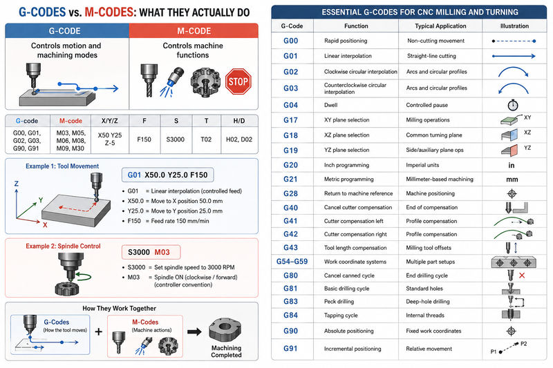
G-codes are generally used to control tool movement, positioning, machining modes, coordinate systems, compensation, and machining cycles. M-codes primarily control machine-related auxiliary functions, such as spindle rotation, coolant, tool changes, stops, and program termination.
A useful way to remember the difference is:
| Code Type | Main Purpose | Typical Examples |
|---|---|---|
| G-code | Controls motion and machining modes | G00, G01, G02, G03, G90, G91 |
| M-code | Controls machine functions | M03, M05, M06, M08, M09, M30 |
| X/Y/Z | Defines tool position | X50 Y25 Z-5 |
| F | Defines feed rate | F150 |
| S | Defines spindle speed | S3000 |
| T | Selects tool | T02 |
| H/D | Applies tool compensation | H02, D02 |
Consider this simple block:
G01 X50.0 Y25.0 F150
The G01 tells the machine to perform a controlled linear movement. X50.0 and Y25.0 specify the destination, while F150 specifies the programmed feed rate.
Now consider:
S3000 M03
S3000 establishes a spindle speed of 3,000 RPM, while M03 commands the spindle to rotate in the forward/clockwise direction on controllers where M03 has that conventional meaning.
The two command groups therefore work together. G-codes determine how the cutting tool moves, while M-codes determine many of the machine’s supporting actions.
This distinction becomes particularly important when troubleshooting a CNC program. If the tool moves to the wrong position, the problem may involve a G-code, coordinate system, work offset, or tool compensation. If the spindle does not rotate or coolant does not activate, the problem is more likely related to an M-code or machine configuration.
Essential G-Codes for CNC Milling and Turning
G-codes cover many different operations, but a relatively small group appears repeatedly in everyday CNC machining.
| G-Code | Function | Typical Application |
|---|---|---|
| G00 | Rapid positioning | Non-cutting movement |
| G01 | Linear interpolation | Straight-line cutting |
| G02 | Clockwise circular interpolation | Arcs and circular profiles |
| G03 | Counterclockwise circular interpolation | Arcs and circular profiles |
| G04 | Dwell | Controlled pause |
| G17 | XY plane selection | Milling operations |
| G18 | XZ plane selection | Common turning plane |
| G19 | YZ plane selection | Side/auxiliary plane operations |
| G20 | Inch programming | Imperial units |
| G21 | Metric programming | Millimeter-based machining |
| G28 | Return to machine reference | Machine positioning |
| G40 | Cancel cutter compensation | End of compensation |
| G41 | Cutter compensation left | Profile compensation |
| G42 | Cutter compensation right | Profile compensation |
| G43 | Tool length compensation | Milling tool offsets |
| G54-G59 | Work coordinate systems | Multiple part setups |
| G80 | Cancel canned cycle | End drilling cycle |
| G81 | Basic drilling cycle | Standard holes |
| G83 | Peck drilling | Deep-hole drilling |
| G84 | Tapping cycle | Internal threads |
| G90 | Absolute positioning | Fixed work coordinates |
| G91 | Incremental positioning | Relative movement |
These functions are widely represented in CNC programming references, although the exact implementation can depend on the controller and machine configuration.
G00 and G01: The Two Fundamental Motion Commands
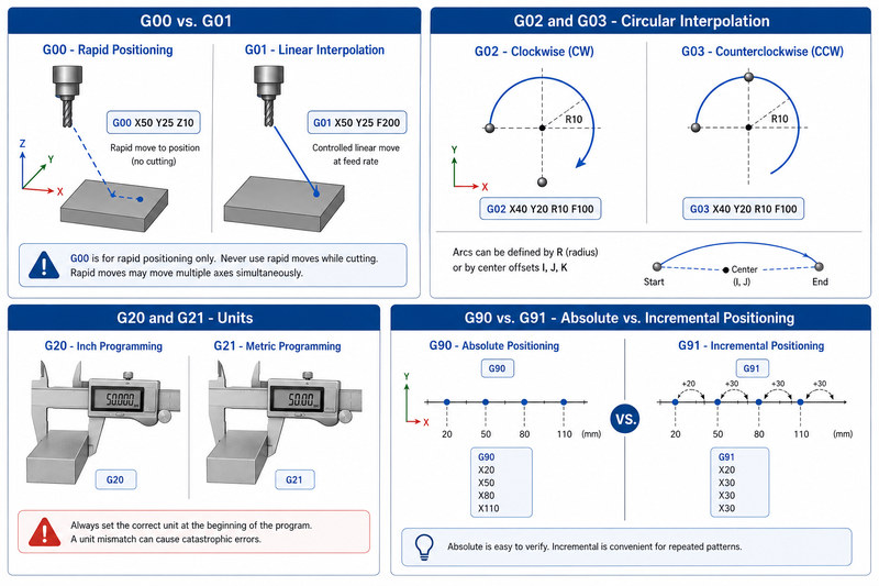
G00 is normally used for rapid positioning. It moves the tool toward a programmed position without intending to perform cutting.
For example:
G00 X50 Y25 Z10
This command positions the tool at X50, Y25, Z10 using the machine’s rapid positioning mode.
G01 is different because it performs controlled linear interpolation:
G01 X50 Y25 F200
Here, the tool travels toward the programmed coordinate at the specified feed rate.
One important practical point is that G00 should not normally be treated as a cutting command. Rapid movement is intended to reduce non-cutting time. Using rapid positioning while the tool is expected to be engaged in material can create a serious collision or cutting-condition problem. Some controllers also move multiple axes simultaneously during rapid positioning rather than following the same controlled straight-line path a programmer might expect.
G02 and G03: Creating Circular Geometry
G02 and G03 are used for circular interpolation.
G02 X40 Y20 R10 F100
G02 represents clockwise circular interpolation.
G03 X40 Y20 R10 F100
G03 represents counterclockwise circular interpolation.
Depending on the controller and programming format, arcs can be defined using an R value or center-offset values such as I, J, and K. I, J, and K define the arc center relative to the starting point in the relevant coordinate planes.
For precision CNC machining, this matters because a small programming error in arc geometry can change the resulting radius, endpoint, or toolpath. For a component containing bearing seats, sealing grooves, or precision circular pockets, these differences can directly affect dimensional accuracy.
G20 and G21: Units Must Be Defined Correctly
G20 normally selects inch programming, while G21 selects metric programming.
For example:
G21
G01 X50.0 F200
means the program is working in millimeters under the conventional interpretation.
A unit mismatch can create a catastrophic machining error. A coordinate intended as 50 mm could effectively be interpreted under an inch-based program as 50 inches. For that reason, experienced programmers normally establish the intended unit system near the beginning of a program rather than relying on whatever mode the machine happened to retain from the previous program.
G90 and G91: Absolute vs. Incremental Positioning
G90 uses absolute positioning, meaning coordinates are referenced to the active work coordinate system.
For example:
G90
G00 X50 Y30
The tool moves to the programmed X50 Y30 location.
G91 uses incremental positioning. The next movement is calculated from the tool’s current position.
G91
G01 X10 Y0 F100
This means move 10 units in X from the current position.
The difference becomes important when programming repeated features. Suppose four holes are located at X20, X50, X80, and X110 mm.
An absolute approach could specify each position directly:
G90
X20
X50
X80
X110
An incremental approach could use the distances between holes:
G91
X20
X30
X30
X30
Neither method is automatically better. Absolute positioning is often easier to verify against a drawing, while incremental positioning can be convenient for repetitive patterns.
Essential M-Codes for Spindle, Coolant, Tool Changes, and Program Control
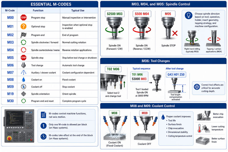
M-codes control machine functions that generally do not command axis motion. Haas documentation specifies that M-codes are miscellaneous machine commands and that, on its systems, only one M-code is allowed per block and M-codes take effect at the end of the block.
Common M-codes include:
| M-Code | Function | Typical Use |
|---|---|---|
| M00 | Program stop | Manual inspection or intervention |
| M01 | Optional stop | Inspection when optional stop is enabled |
| M02 | Program end | End of program |
| M03 | Spindle clockwise/forward | Normal cutting rotation |
| M04 | Spindle counterclockwise/reverse | Reverse rotation applications |
| M05 | Spindle stop | Stop before tool change or shutdown |
| M06 | Tool change | Automatic tool change |
| M07 | Auxiliary/shower coolant | Coolant configuration dependent |
| M08 | Coolant on | Flood coolant |
| M09 | Coolant off | Stop coolant |
| M19 | Spindle orientation | Orient spindle |
| M30 | Program end and reset | Complete program cycle |
Haas’ published mill M-code list confirms these commonly used functions while also showing that additional M-codes can control machine-specific functions such as chip conveyors, pallet systems, brakes, and gear selection.
M03, M04, and M05: Spindle Control
A typical spindle startup sequence might be:
S2500 M03
The S-word specifies spindle speed and M03 starts forward/clockwise rotation.
To stop the spindle:
M05
Reverse rotation is normally commanded using:
S500 M04
However, spindle direction should never be selected simply because a code appears in a reference table. The correct direction depends on the tool, machining operation, holder, insert geometry, tapping strategy, and machine configuration.
For example, a standard right-hand milling operation will normally use conventional spindle rotation, while certain tapping or left-hand tooling applications may require reverse rotation.
M06: Tool Changes
A common tool-change command is:
T02 M06
This tells the CNC control to select tool number 2 and execute the tool-change operation under the controller’s programming convention.
A realistic milling sequence could look like:
T01 M06
S3000 M03
The machine first loads Tool 1 and then starts the spindle at 3,000 RPM.
Tool selection is closely related to tool length compensation. On many vertical machining centers, a tool-change sequence is followed by a command such as:
G43 H01 Z50
Here G43 activates positive tool length compensation and H01 selects the corresponding tool length offset.
If the tool offset table is incorrect, even perfectly written XYZ coordinates can produce incorrect cutting depth.
M08 and M09: Coolant Control
M08 commonly turns flood coolant on:
M08
M09 turns coolant off:
M09
Coolant is not simply an optional convenience. For many metals, proper coolant delivery affects cutting temperature, chip evacuation, tool life, surface finish, and dimensional stability.
For example, when milling aluminum at relatively high material-removal rates, adequate coolant or an appropriate chip-evacuation strategy can help prevent chips from being recut. During stainless steel machining, coolant management can also influence heat accumulation and tool wear.
The exact coolant behavior depends on the CNC machine’s hardware. Some machines have flood coolant, mist, through-tool coolant, air blast, or combinations of these functions.
M00, M01, and M30: Program Control
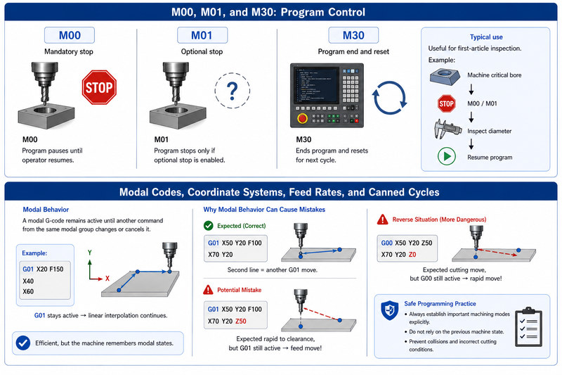
M00 creates a mandatory program stop.
M00
The machine pauses until the operator resumes the program.
M01 is an optional stop:
M01
It only causes a stop when the machine’s optional-stop function is enabled.
These commands can be useful for first-article inspection. For example, after machining a critical bore, the program could stop so the operator can measure the diameter before allowing the next operation to continue.
M30 is commonly used to end a CNC program and reset it for another cycle:
M30
Haas documentation identifies M30 as “Program End and Reset.”
Modal Codes, Coordinate Systems, Feed Rates, and Canned Cycles
Understanding modal behavior is one of the most important steps in moving from basic G-code memorization to practical CNC programming.
A modal G-code remains active until another command from the same modal group changes or cancels it. Autodesk explains that modal groups allow multiple codes on one line while restricting multiple commands from the same group.
For example:
G01 X20 F150
X40
X60
If G01 remains active, the second and third blocks can continue using linear interpolation without repeating G01.
That is efficient, but it also creates a potential programming hazard: the machine remembers modal states.
Why Modal Behavior Can Cause Mistakes
Consider:
G01 X50 Y20 F100
X70 Y20
The second line is interpreted as another G01 movement if the controller is still in G01 mode.
Now imagine that a programmer expected the machine to rapid to a clearance position but forgot to command G00:
X70 Y20 Z50
The tool may perform a feed move instead of a rapid move.
The reverse situation can be even more dangerous. If a programmer assumes a cutting mode is active while the machine remains in rapid positioning, the tool could move toward the workpiece at rapid speed.
For this reason, safe CNC programming often begins by deliberately establishing important machining modes instead of relying on the previous machine state.
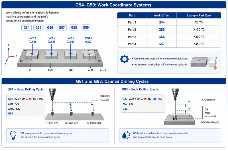
G54-G59: Work Coordinate Systems
Work offsets define the relationship between machine coordinates and the part’s programmed coordinate system.
Common work offsets include:
G54
G55
G56
G57
G58
G59
These allow multiple fixtures or part locations to be programmed without changing the underlying machine coordinate system.
For example, four identical parts may be mounted on one fixture. Each part can use a different work offset:
| Part | Work Offset | Example Part Zero |
|---|---|---|
| Part 1 | G54 | X0 Y0 |
| Part 2 | G55 | X150 Y0 |
| Part 3 | G56 | X300 Y0 |
| Part 4 | G57 | X450 Y0 |
This approach can significantly improve production efficiency because the same machining program can be reused for multiple work locations.
However, an incorrect work offset can shift the entire toolpath. If the program is correct but G54 is incorrectly measured, the machine may cut the entire part in the wrong location.
G81 and G83: Canned Drilling Cycles
Canned cycles reduce repetitive programming.
A basic drilling operation could otherwise require separate positioning, approach, cutting, and retract commands for every hole.
G81 compresses a basic drilling operation into a reusable cycle. Autodesk describes canned cycles as a way to incorporate multiple movements into a single command, significantly reducing the amount of repeated code.
A simplified example is:
G81 X20 Y20 Z-10 R2 F100
X60 Y20
X100 Y20
G80
The first G81 line establishes the drilling cycle. The following coordinates define additional hole locations while the cycle remains active. G80 cancels the drilling cycle.
For deeper holes, G83 is commonly used for peck drilling:
G83 X20 Y20 Z-30 R2 Q5 F80
Here Q5 represents a 5-unit peck increment under the applicable controller’s syntax.
Peck drilling is useful when chip evacuation and heat control become difficult, particularly in deeper holes or materials that generate long chips.
Feed Rate: F Is Not Just a Number
The F-word specifies feed rate, but its interpretation depends on the active feed mode and controller.
For milling, a common mode is feed per minute:
G94
G01 X50 F200
This means a feed rate of 200 units per minute under the selected unit system.
For turning and other applications, feed per revolution may be used:
G95
The actual cutting conditions must be determined from the tool diameter, material, cutter geometry, number of teeth, spindle speed, depth of cut, width of cut, machine rigidity, and tooling manufacturer’s recommendations.
For example, increasing spindle speed without considering feed per tooth can produce an inappropriate chip load. Conversely, reducing feed while maintaining a high spindle speed can cause rubbing rather than efficient cutting.
Therefore, G-code defines the commanded movement, but it does not automatically determine whether the cutting conditions are appropriate for the material.
A Practical CNC Program Example
The following simplified example demonstrates how G-codes and M-codes work together on a three-axis machining center.
%
O1001
G21 G17 G90 G40 G49 G80
G54
T01 M06
S3000 M03
G00 G43 H01 Z50
M08
G00 X20 Y20
G01 Z-2 F100
G01 X80 F250
G01 Y60
G01 X20
G01 Y20
G00 Z50
M09
M05
G91 G28 Z0
G90
M30
%
This example can be broken down into several stages.
| Program Block | Purpose |
|---|---|
| G21 | Select millimeter programming |
| G17 | Select XY plane |
| G90 | Select absolute positioning |
| G40 | Cancel cutter compensation |
| G49 | Cancel tool length compensation |
| G80 | Cancel canned cycle |
| G54 | Select work offset |
| T01 M06 | Load Tool 1 |
| S3000 M03 | Start spindle at 3,000 RPM |
| G00 G43 H01 Z50 | Apply tool length offset and move to safe Z |
| M08 | Start coolant |
| G00 X20 Y20 | Rapid to the machining start position |
| G01 Z-2 F100 | Feed into material |
| G01 X80 F250 | Machine straight line |
| G00 Z50 | Retract |
| M09 | Coolant off |
| M05 | Spindle stop |
| G91 G28 Z0 | Return Z through the reference sequence |
| G90 | Restore absolute positioning |
| M30 | End and reset program |
The exact syntax and safety of a production program must always be verified against the specific CNC controller, machine, tooling, workholding, and setup. A sample program should not be copied directly into a production machine without simulation and verification.
Common G-Code and M-Code Programming Mistakes
Forgetting the Active Coordinate Mode
A programmer may intend to use absolute positioning but leave the controller in incremental mode.
For example:
G91
X50
does not mean “go to X50” in the same way that G90 X50 does. It means move 50 units from the current position.
Before running a program, verify whether the intended mode is G90 or G91.
Forgetting to Cancel a Canned Cycle
If G81 or G83 remains active and the programmer intends to make an ordinary positioning move, the controller may interpret subsequent coordinates as additional drilling locations.
A common practice is:
G80
after the drilling operation.
Using the Wrong Tool Offset
Consider:
T03 M06
G43 H03 Z50
If Tool 3 is physically loaded but H03 contains the wrong measured tool length, the machine’s actual tool tip position will not match the programmer’s expected position.
Tool measurement is therefore just as important as the G-code itself.
Incorrect Spindle Speed or Direction
A program can contain perfectly valid syntax and still be unsuitable for the cutting tool.
For example:
S12000 M03
may be appropriate for one small carbide end mill but completely inappropriate for a large cutter, depending on its maximum RPM and recommended cutting speed.
Likewise, the correct spindle direction depends on the tool and machining operation.
Confusing G00 With G01
This is one of the most fundamental distinctions in CNC programming.
G00 X100
is a rapid positioning command.
G01 X100 F200
is a controlled feed movement.
Using the wrong one can affect both cycle time and machining safety.
How G-Codes and M-Codes Affect CNC Part Quality
G-codes and M-codes do not directly determine whether a finished component will meet its drawing tolerances. Instead, they form the execution layer connecting the CAM strategy, machine setup, tooling, workholding, and physical cutting process.
For example, achieving a ±0.01 mm dimensional requirement may involve:
- Correct work offset measurement
- Accurate tool length and diameter compensation
- Appropriate cutter selection
- Proper spindle speed
- Correct feed rate
- Controlled depth of cut
- Stable workholding
- Suitable coolant delivery
- Machine thermal stability
- Tool wear compensation
- Accurate inspection
The G-code may specify:
G01 X50.000 F150
but the physical result depends on the entire machining system.
This is why experienced CNC manufacturers do not treat programming as an isolated activity. The program must be evaluated together with the material, geometry, tolerance, tooling, machine capability, and inspection requirements.
G-Codes and M-Codes in Modern CNC Manufacturing
Modern CNC manufacturing increasingly relies on CAM software to generate G-code automatically from CAD geometry. However, automatic generation does not eliminate the need for CNC programming knowledge.
A machinist or manufacturing engineer still needs to understand the resulting code to verify:
- Tool selection
- Work offsets
- Safe approach and retract positions
- Cutting direction
- Spindle speed
- Feed rate
- Coolant commands
- Tool compensation
- Canned cycles
- Program stops
- Program end conditions
This becomes particularly important when manufacturing complex parts with multiple tools, tight tolerances, deep pockets, thin walls, curved surfaces, or multiple setups.
For example, a five-axis machining center may generate thousands of lines of toolpath data. The code may be generated automatically, but understanding the underlying coordinate systems, tool orientation, compensation, and machine behavior remains essential for safe production.
Choosing a CNC Manufacturing Partner With the Right Programming Capability
For customers ordering custom CNC machined components, understanding G-codes and M-codes provides a useful perspective on what happens between a CAD drawing and a finished metal part.
A professional CNC manufacturer should be able to translate technical drawings and 3D CAD models into a reliable machining process rather than simply run a generic toolpath. Material selection, machine configuration, tooling, workholding, tolerance requirements, surface finish, inspection, and programming all need to work together.
At Xavier, CNC machining is approached as an integrated manufacturing process. Whether the requirement involves CNC milling, CNC turning, precision metal components, prototypes, or production parts, the machining program needs to be matched to the actual material, geometry, tolerance, and production requirements.
Understanding G-codes and M-codes is ultimately about more than memorizing commands. G00, G01, G02, G03, G90, G91, G54, G81, M03, M05, M06, M08, and M30 are only individual pieces of a larger manufacturing system. When those commands are correctly combined with suitable tooling, cutting parameters, machine setup, and inspection, they become the digital instructions that turn a CAD design into a precise physical component.
For customers looking for dependable CNC machining services, the real value lies not simply in whether a manufacturer can generate G-code, but in whether its engineers and machinists understand what that code will do to the material on the machine—and can control the entire process from drawing review through finished-part inspection.
We are an integrated CNC machining manufacturer specializing in CNC contract manufacturing and the production of a wide range of custom metal components. Our capabilities cover materials such as alloy steel, aluminum, brass, bronze, copper, Inconel, Invar 36, low carbon steel, stainless steel, titanium, tool steel, ABS, FR4, G-10, nylon, PEEK, PEI, PET, PMMA (acrylic), polycarbonate, polyethylene, polypropylene, POM (acetal), PPSU, PTFE (Teflon), and PVC. We provide precision machining solutions for robot components, aerospace parts, marine components, automotive parts, medical components, and other precision-engineered parts, including CNC machining PEEK, CNC machining brass, and CNC machining titanium.
CNC machining PEEK manufacturer with extensive production experience, offering CNC machining brass services for various industrial applications. CNC machining titanium pricing can be provided based on your drawings, material requirements, quantities, and machining specifications. Feel free to contact us for your custom CNC machining needs.
Some of the images and text in this article are collected and compiled from the internet. If there is anything inappropriate, please contact us for processing.