
Complex Part Machining: Processes, Materials, Precision, Challenges, and Manufacturing Solutions
Complex part machining is an advanced manufacturing process used to produce components with intricate geometries, multiple machining surfaces, tight dimensional tolerances, and demanding functional requirements. These components are commonly found in aerospace, automotive, medical equipment, robotics, industrial machinery, and precision engineering applications.
Unlike conventional CNC machining, complex part machining often requires a combination of multi-axis milling, CNC turning, drilling, boring, grinding, and specialized workholding solutions. The challenge is not simply producing the required shape but maintaining dimensional accuracy, surface quality, and consistency throughout the entire manufacturing process.
For engineers and purchasing professionals, understanding machining capabilities, material behavior, production methods, and quality control is essential when selecting a reliable manufacturing partner.
1. What Is Complex Part Machining?
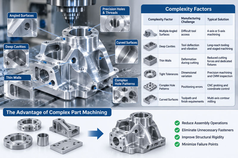
Complex part machining refers to the manufacturing of components with geometries or technical requirements that cannot be efficiently produced through standard machining operations alone. These parts may contain multiple angled surfaces, deep pockets, narrow slots, curved profiles, precision holes, internal threads, and thin structural sections.
A typical example is an aerospace equipment housing containing multiple mounting surfaces, intersecting holes, internal channels, and accurately positioned bearing seats. Although these features may appear straightforward in a CAD model, producing them requires careful consideration of tool accessibility, machining sequences, positioning accuracy, and material deformation.
The complexity of a component is generally determined by several factors:
| Complexity Factor | Manufacturing Challenge | Typical Solution |
|---|---|---|
| Multiple angled surfaces | Difficult tool access | 4-axis or 5-axis machining |
| Deep cavities | Tool deflection and vibration | Long-reach tooling and staged machining |
| Thin walls | Deformation during cutting | Reduced cutting forces and dedicated fixtures |
| Tight tolerances | Dimensional variation | Precision machining and CMM inspection |
| Complex hole patterns | Positioning errors | CNC probing and coordinate control |
| Curved surfaces | Toolpath and finish requirements | Multi-axis contour milling |
Complex part machining is particularly valuable when several individual components can be consolidated into one precision-machined component. This can reduce assembly operations, eliminate unnecessary fasteners, improve structural rigidity, and minimize potential failure points.
2. 3-Axis vs. 4-Axis vs. 5-Axis CNC Machining
Selecting the appropriate CNC machine is one of the most important decisions in complex part manufacturing. Different machine configurations provide different levels of accessibility, positioning flexibility, and production efficiency.
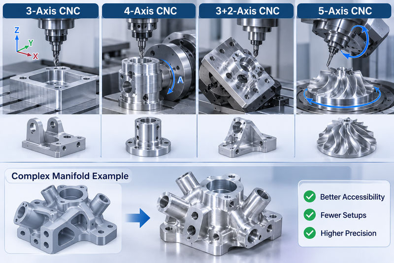
3-axis CNC machining moves the cutting tool along the X, Y, and Z axes. It is suitable for components with relatively straightforward geometries, including mounting plates, housings, brackets, pockets, and drilled surfaces. However, parts requiring machining on several sides may need repeated repositioning.
4-axis CNC machining introduces a rotary axis, allowing the workpiece to rotate during machining. This is useful for cylindrical components, radial hole patterns, and parts with features distributed around multiple surfaces.
5-axis CNC machining adds another rotary axis, allowing the cutting tool or workpiece to change orientation in more directions. This makes it particularly useful for compound angles, complex contours, impellers, turbine components, and deep cavities.
| Machining Method | Main Capability | Suitable Applications |
|---|---|---|
| 3-axis | Linear movement in three directions | Plates, pockets, basic housings |
| 4-axis | Three linear axes plus one rotary axis | Cylindrical parts, radial features |
| 3+2-axis | Five-axis positioning with fixed tool orientation during cutting | Multi-face components |
| Simultaneous 5-axis | Five coordinated axes during cutting | Freeform surfaces, impellers, compound geometries |
For example, a complex aluminum manifold with angled ports and multiple mounting faces may require several setups on a conventional 3-axis machine. A 5-axis machining center can access many of these features with fewer repositioning operations.
However, five-axis machining is not automatically the best solution for every complex component. Machine programming, fixture design, tool accessibility, and production volume must all be considered. The most economical process is the one that meets the drawing requirements with reliable repeatability.
3. Design for Manufacturability (DFM) in Complex Part Machining
Design for Manufacturability, commonly known as DFM, is the process of optimizing a component’s design so that it can be manufactured accurately, efficiently, and economically.
In complex CNC machining, DFM evaluation should take place before production programming begins. A part may be geometrically achievable but still require excessive machining time because of unnecessary deep pockets, inaccessible internal corners, unusually small radii, or complicated clamping requirements.
Several design considerations can significantly improve manufacturability.
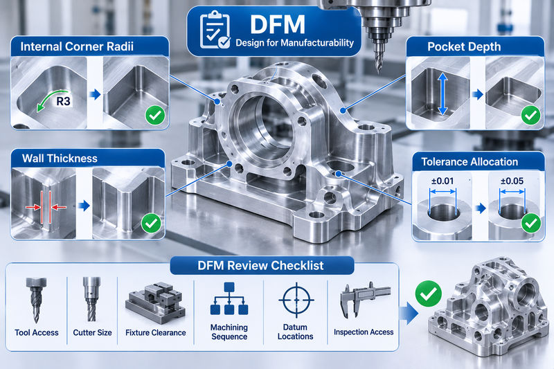
Internal corner radii: CNC milling cutters are circular, so they cannot create perfectly sharp internal corners through conventional milling. Designers should provide practical corner radii that match available tooling. For example, an internal radius of R3 mm may allow the use of a larger and more rigid cutter than R0.5 mm, depending on the geometry.
Pocket depth: Deep pockets require longer cutting tools. Increasing tool overhang reduces rigidity and increases the risk of vibration and dimensional deviation. Where possible, designers should reduce unnecessary pocket depth or divide complex internal structures into more accessible features.
Wall thickness: Thin sections can deform under cutting forces and clamping pressure. Supporting the component during machining and removing material in balanced stages can reduce distortion.
Tolerance allocation: Not every dimension needs extremely tight tolerances. Applying ±0.01 mm to every feature may increase inspection time and production costs without improving the component’s actual functionality.
A practical DFM review should evaluate tool access, cutter diameter, fixture clearance, machining sequence, datum locations, and inspection accessibility together.
4. Precision Tolerances and GD&T Requirements
Dimensional accuracy is a major requirement in complex part machining, particularly when components must fit together with bearings, shafts, seals, fasteners, or other precision assemblies.
However, dimensional tolerance and geometric tolerance are not the same thing. A hole may meet its specified diameter while still being incorrectly positioned relative to another feature.
Geometric Dimensioning and Tolerancing (GD&T) provides a systematic method of controlling these relationships.
Common requirements include:
- Position tolerance: Controls the actual location of holes, slots, and other features relative to established datums.
- Flatness: Controls the deviation of a surface from an ideal plane.
- Parallelism: Ensures two surfaces or axes maintain the required orientation.
- Perpendicularity: Controls the relationship between surfaces or axes at approximately 90 degrees.
- Concentricity and coaxiality: Address the alignment relationship between rotational features, where specified.
- Profile tolerance: Controls the deviation of complex curved or irregular surfaces.
The following table provides illustrative tolerance ranges. Actual capabilities depend on material, component geometry, machine condition, setup, measurement method, and production requirements.
| Feature | Illustrative Precision Range | Important Consideration |
|---|---|---|
| General machined dimensions | ±0.05 mm | Standard production requirements |
| Precision dimensions | ±0.01 mm | Requires process control |
| Selected precision bores | ±0.005–0.01 mm | Tooling and measurement are critical |
| Surface flatness | 0.01–0.05 mm | Depends on size and geometry |
| Complex surface profile | 0.02–0.05 mm | Requires suitable inspection methods |
Consider a precision gearbox housing with multiple bearing bores. Even if every bore has an acceptable diameter, incorrect positional relationships can cause shaft misalignment, excessive vibration, and premature bearing wear.
Therefore, critical dimensions should be identified on engineering drawings, and inspection methods should be selected according to the functional requirements rather than applying the same tolerance to every feature.
5. Workholding and Fixture Design for Complex Components
Workholding is one of the most challenging aspects of complex part machining. Unlike simple plates or cylindrical stock, complicated components may have irregular shapes, limited clamping surfaces, thin walls, and features that need to remain accurately aligned across multiple machining operations.
Poor fixture design can introduce deformation before cutting even begins.
For example, when machining a thin-wall aluminum housing, excessive clamping pressure may cause the component to deform. Once the fixture is released, the material can partially recover, leaving the finished dimensions outside the required tolerance.
Several workholding methods are commonly used:
Custom fixtures: Dedicated fixtures are designed around the component’s geometry, providing repeatable positioning and stable support.
Soft jaws: Machined jaws can match the external shape of a component and distribute clamping forces more evenly.
Vacuum fixtures: Suitable for certain flat, thin, or non-ferrous components with sufficient sealing surfaces.
Modular fixtures: Adjustable locating and clamping elements are useful for prototypes and low-volume production.
A reliable fixture strategy should establish stable datum references, minimize unnecessary repositioning, provide adequate tool clearance, and avoid excessive clamping forces.
For components requiring machining on several sides, 4-axis or 5-axis setups can reduce repeated clamping and help maintain relationships between critical features.
6. Machining Difficult Materials for Complex Parts
Material selection has a direct influence on cutting parameters, tool life, surface finish, dimensional stability, and overall production costs.
Different materials respond differently to cutting forces and heat. Therefore, complex part machining requires material-specific tooling, cutting strategies, and cooling methods.
| Material | Key Characteristics | Machining Considerations | Common Applications |
|---|---|---|---|
| Aluminum 6061-T6 | Lightweight, good machinability | Control burrs and thin-wall deformation | Housings, brackets |
| Aluminum 7075-T6 | High strength-to-weight ratio | Manage residual stress and distortion | Aerospace structures |
| Stainless Steel 304 | Corrosion resistance | Avoid work hardening and excessive heat | Industrial equipment |
| Stainless Steel 316 | Excellent corrosion resistance | Use appropriate cutting tools and coolant | Marine and medical equipment |
| Titanium Grade 5 | High strength and low density | Control heat, tool wear, and cutting speed | Aerospace components |
| Inconel 718 | High-temperature strength | Requires rigid setups and specialized tooling | Turbine and aerospace parts |
| PEEK | High-performance engineering plastic | Control heat and dimensional changes | Medical and industrial components |
Aluminum alloys are frequently selected for complex components because of their relatively good machinability and low density. However, thin aluminum walls can deform easily when subjected to cutting forces or excessive clamping pressure.
Titanium and Inconel present different challenges. Their strength and thermal properties can generate high cutting temperatures and accelerate tool wear. Appropriate cutting speeds, rigid toolholders, controlled chip evacuation, and effective coolant delivery are essential.
For engineering plastics such as PEEK, machining temperature and stress release must also be controlled. Excessive heat can cause dimensional instability, while unsuitable clamping can damage the finished surface.
7. Machining Thin Walls, Deep Cavities, and Complex Geometries
Thin walls and deep cavities are among the most difficult features in complex part machining because they reduce structural rigidity and limit tool accessibility.
Thin-wall machining is particularly challenging when manufacturing lightweight aerospace brackets, aluminum housings, and structural components. As material is removed, the remaining wall becomes less rigid and more susceptible to vibration and deformation.
A practical strategy is to leave additional material during rough machining and remove it during subsequent finishing operations. Alternating between different machining regions can also help balance internal stresses.
Deep cavity machining presents another challenge. Long-reach tools are often necessary to reach the bottom of narrow pockets, but longer tools are more susceptible to deflection and chatter.
To improve machining stability:
- Use the shortest practical cutting tool.
- Select a tool diameter suitable for the cavity width.
- Apply appropriate step-over and step-down values.
- Use staged roughing and finishing operations.
- Ensure chips can escape without accumulating inside the cavity.
Complex curved surfaces require careful toolpath planning. Ball-nose cutters are commonly used for three-dimensional contours, while suitable flat-end or bull-nose cutters may improve efficiency on accessible surfaces.
For example, an impeller with multiple curved blades requires controlled tool orientation to avoid collisions while maintaining consistent surface quality. This is one of the applications where simultaneous five-axis machining can provide significant advantages.
8. Multi-Process CNC Machining Strategies
Complex components rarely depend on a single manufacturing process. Combining several machining methods can provide better dimensional control, improve productivity, and reduce unnecessary operations.
A typical manufacturing route may include:
| Manufacturing Stage | Process | Main Purpose |
|---|---|---|
| 1 | Material preparation | Select and prepare suitable stock |
| 2 | CNC rough milling | Remove excess material |
| 3 | CNC turning | Produce rotational features |
| 4 | Drilling and boring | Create accurate holes and bores |
| 5 | 4-axis or 5-axis milling | Machine angled and complex surfaces |
| 6 | Stress-relief treatment, if required | Reduce distortion risk |
| 7 | Finish milling and grinding | Achieve final dimensions |
| 8 | Deburring and surface treatment | Improve edges and surface condition |
| 9 | Final inspection | Verify drawing requirements |
For example, a precision hydraulic valve body may require milling for external surfaces, deep-hole drilling for internal passages, boring for precision valve bores, and grinding for selected functional surfaces.
Electrical Discharge Machining (EDM) may also be used when conventional cutting tools cannot efficiently produce narrow slots, sharp internal details, or certain difficult geometries. However, EDM is generally limited to electrically conductive materials.
The manufacturing sequence must be planned carefully. Machining critical datums too early, applying surface treatments before final precision operations, or removing too much material in one stage can create avoidable quality problems.
9. Surface Finish and Quality Inspection
A complex component is not considered complete simply because its dimensions meet the drawing. Surface finish, edge conditions, hole quality, geometric relationships, and material requirements must also be verified.
Surface roughness is commonly evaluated using Ra, which represents the arithmetic average deviation of a measured surface profile.
| Surface Condition | Illustrative Ra Value | Typical Application |
|---|---|---|
| Standard machined finish | 3.2 μm | General mechanical surfaces |
| Improved machined finish | 1.6 μm | Functional mating surfaces |
| Fine machined finish | 0.8 μm | Precision components |
| Ground finish | 0.4 μm or finer | Selected precision interfaces |
These values are general reference points rather than guaranteed results for every geometry. The required finish should be specified according to sealing, sliding, friction, appearance, and assembly requirements.
Quality inspection may involve several instruments and methods:
- CMM inspection: Measures complex geometries, hole positions, and relationships between multiple datums.
- Micrometers: Verify external dimensions with higher precision than general-purpose calipers.
- Bore gauges: Check internal diameters and bore consistency.
- Height gauges: Measure feature positions relative to a reference surface.
- Surface roughness testers: Evaluate surface texture against specified Ra requirements.
- Optical measurement systems: Inspect small features and complex profiles.
For demanding applications, first article inspection (FAI), material certificates, dimensional reports, and batch traceability may also be required.
An effective inspection plan should identify critical dimensions before production begins. This prevents situations where an important internal feature becomes difficult to measure after the surrounding geometry has been completed.
10. Complex CNC Machining Cost and Production Optimization
The cost of complex part machining depends on more than the amount of raw material used. Geometry, material machinability, machining time, fixture requirements, tolerance levels, surface treatment, and inspection requirements all contribute to the final price.
The main cost factors include:
| Cost Factor | Impact on Manufacturing Cost | Optimization Method |
|---|---|---|
| Complex geometry | More programming and machining time | Simplify non-functional features |
| Difficult materials | Higher tool wear and slower cutting | Select suitable tooling and parameters |
| Tight tolerances | More finishing and inspection | Apply tight tolerances selectively |
| Multiple setups | Increased labor and positioning risk | Use multi-axis machining where justified |
| Thin walls | Slower machining and higher scrap risk | Optimize wall design and cutting sequence |
| Special fixtures | Additional setup investment | Use modular fixtures when practical |
| Surface finishing | Additional processing time | Specify functional finish requirements |
For example, consider an aluminum component with six angled holes, several deep pockets, and two precision bearing bores. Manufacturing it on a conventional 3-axis machine may require multiple setups, additional positioning operations, and repeated inspections.
A suitable 4-axis or 5-axis strategy may reduce repositioning and improve positional consistency. However, the machine cost, programming complexity, and fixture requirements must be evaluated before selecting the final process.
For prototype production, flexible fixtures and efficient engineering preparation may be more economical than investing in dedicated tooling. For recurring production, dedicated fixtures, optimized toolpaths, and standardized inspection procedures can reduce unit costs.
The best approach is to balance machining capability, functional requirements, production quantity, and long-term manufacturing stability.
Why Choose Xavier for Complex Part Machining?
Manufacturing complex components requires more than advanced CNC equipment. It requires engineering knowledge, suitable materials, careful process planning, reliable machining techniques, and consistent quality inspection.
Xavier is a CNC machining service provider and integrated manufacturing and trading factory specializing in custom CNC machining and precision metal components. We support customers looking for custom-machined parts with complex geometries, multiple machining features, and demanding dimensional requirements.
Our manufacturing solutions cover CNC milling, CNC turning, multi-axis machining, precision drilling, boring, grinding, and various surface finishing processes. We work with materials including aluminum, stainless steel, brass, copper, titanium, alloy steel, and engineering plastics.
Whether you need a single prototype, a small production batch, or recurring manufacturing support, our focus is on selecting practical machining methods that meet your technical requirements while controlling production costs.
If you are sourcing complex CNC machined parts, send Xavier your 2D drawings, 3D CAD models, material specifications, and critical tolerance requirements. Our team can review the component geometry, evaluate its manufacturability, and recommend an appropriate production approach.
Contact Xavier today to discuss your complex part machining project and get a customized manufacturing solution for your next precision component.
As an integrated CNC machining manufacturer and trading company, Xavier specializes in custom CNC machining and contract manufacturing of various metal components. We provide comprehensive machining solutions for different materials and applications, including CNC machining PEEK, CNC machining stainless steel, and CNC machining aluminum. Our manufacturing capabilities cover alloy steel, brass, bronze, copper, Inconel, Invar 36, mild steel, aluminum, titanium, tool steel, ABS, FR4, G-10, nylon, PEI, PET, PMMA (acrylic), polycarbonate, polyethylene, polypropylene, POM (acetal), PPSU, PTFE, and PVC. We serve a wide range of industries, manufacturing precision components for robotics, aerospace, marine, automotive, and medical applications.
As a professional CNC machining PEEK manufacturer, we offer bulk CNC machining stainless steel services and provide competitive CNC machining aluminum pricing. Contact us for more information and a customized quotation.
Some of the images and text in this article are collected and compiled from the internet. If there is anything inappropriate, please contact us for processing.