
10 Key Topics to Cover in the Article
1. What Are Tools and Fixtures in CNC Machining?
2. Cutting Tools vs. Fixtures: Functions and Differences
3. CNC Cutting Tool Materials and Tool Selection
4. Common CNC Machining Fixtures and Workholding Methods
5. Fixture Design and the 3-2-1 Locating Principle
6. Clamping Force, Workpiece Deformation, and Machining Stability
7. Tool Selection, Cutting Parameters, and Tool Wear
8. Fixture Accuracy, Repeatability, and Quality Inspection
9. Custom Fixtures for Prototypes and Mass Production
10. How Tools and Fixtures Affect CNC Machining Costs and Lead Times
1. What Are Tools and Fixtures in CNC Machining?
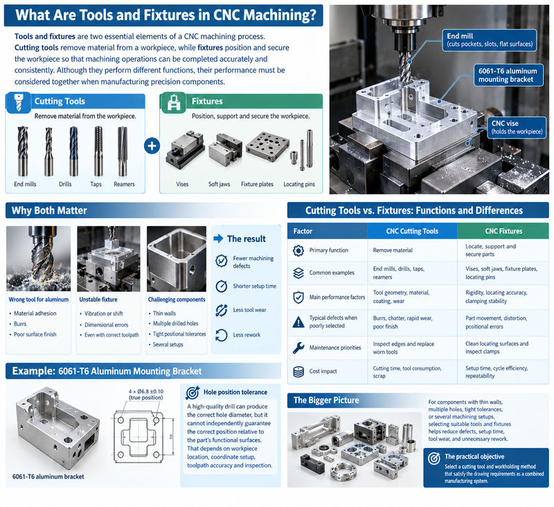
Tools and fixtures are two essential elements of a CNC machining process. Cutting tools remove material from a workpiece, while fixtures position and secure the workpiece so that machining operations can be completed accurately and consistently. Although they perform different functions, their performance must be considered together when manufacturing precision components.
For example, when machining a 6061-T6 aluminum mounting bracket, an end mill may be used to create pockets, slots, and flat surfaces. A CNC vise or a custom fixture holds the aluminum blank in a fixed position during cutting. If the cutting tool is unsuitable for aluminum, material may adhere to the cutting edge, producing burrs and poor surface finish. If the fixture is unstable, the part may vibrate or shift, causing dimensional errors even when the toolpath is correct.
The relationship becomes particularly important when manufacturing components with thin walls, multiple drilled holes, tight positional tolerances, or several machining setups. Selecting suitable tools and fixtures helps reduce machining defects, setup time, tool wear, and unnecessary rework.
2. Cutting Tools vs. Fixtures: Functions and Differences
Cutting tools and fixtures contribute to different aspects of machining performance. A cutting tool determines how material is removed, while the fixture establishes the workpiece’s position and supports it against cutting forces.
| Factor | CNC Cutting Tools | CNC Fixtures |
|---|---|---|
| Primary function | Remove material | Locate, support, and secure parts |
| Common examples | End mills, drills, taps, reamers | Vises, soft jaws, fixture plates, locating pins |
| Main performance factors | Tool geometry, material, coating, wear | Rigidity, locating accuracy, clamping stability |
| Typical defects when poorly selected | Burrs, chatter, rapid wear, poor finish | Part movement, distortion, positional errors |
| Maintenance priorities | Inspect edges and replace worn tools | Clean locating surfaces and inspect clamps |
| Cost impact | Cutting time, tool consumption, scrap | Setup time, cycle efficiency, repeatability |
Consider a component requiring four holes with a true position tolerance of 0.10 mm relative to a machined datum. A high-quality drill can produce the correct hole diameter, but it cannot independently guarantee that the holes are positioned correctly relative to the part’s functional surfaces. That depends on workpiece location, coordinate setup, toolpath accuracy, and inspection.
The same principle applies to surface finish. A sharp finishing end mill may produce an excellent surface on a rigidly supported component, but the result can deteriorate when the workpiece flexes under cutting pressure.
The practical objective is to select a cutting tool and workholding method that satisfy the drawing requirements as a combined manufacturing system.
3. CNC Cutting Tool Materials and Tool Selection
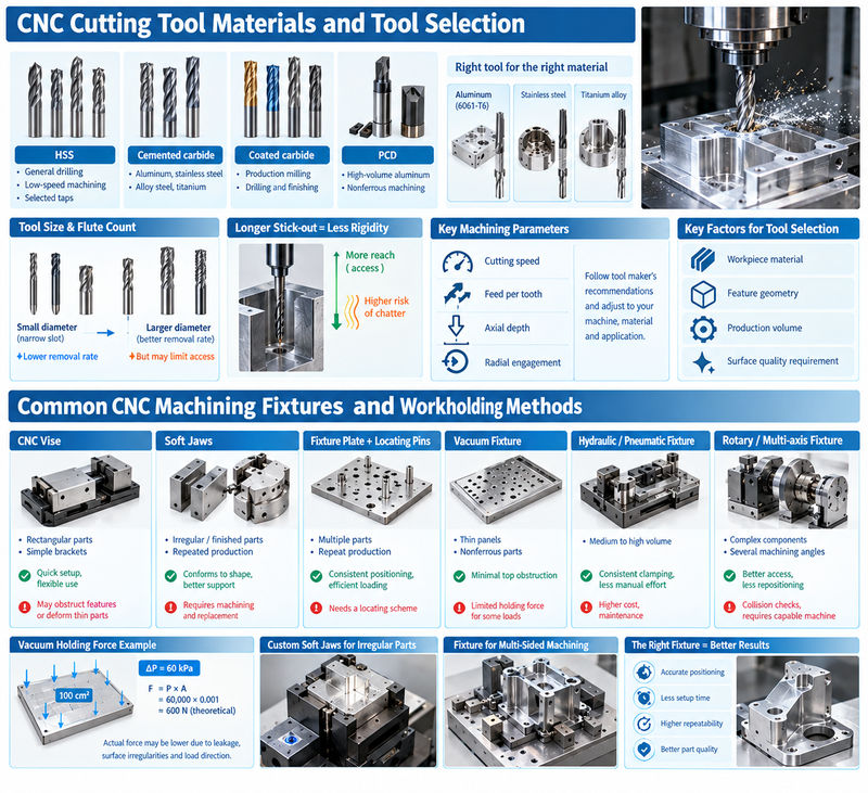
Cutting tool material affects hardness, wear resistance, heat tolerance, cutting speed, and the ability to maintain a sharp edge. The correct choice depends on the workpiece material, feature geometry, production volume, and required surface quality.
| Tool material | Typical applications | Main considerations |
|---|---|---|
| High-speed steel (HSS) | General drilling, low-speed machining, selected taps | Tough and economical, but generally less wear-resistant than carbide |
| Cemented carbide | Aluminum, stainless steel, alloy steel, titanium | High hardness and hot-hardness; requires suitable machine rigidity |
| Coated carbide | Production milling, drilling, and finishing | Coating can improve wear resistance and reduce friction when matched to the application |
| Polycrystalline diamond (PCD) | High-volume aluminum and nonferrous machining | Excellent wear resistance, but higher initial cost and limited suitability for ferrous materials |
Aluminum alloys such as 6061-T6 are commonly machined using sharp carbide tools with geometries designed to promote chip evacuation and reduce built-up edge. For stainless steel, tool selection must account for work hardening and heat concentration. Titanium alloys generally require careful control of cutting speed, engagement, coolant strategy, and tool overhang because heat is concentrated near the cutting edge.
Tool diameter and flute count also matter. A small-diameter end mill used for a narrow slot cannot normally remove material at the same rate as a larger cutter. However, increasing cutter diameter may prevent access to internal corners or narrow features.
For instance, a deep pocket in an aluminum housing may require a long-reach end mill. Increasing tool stick-out provides access, but also reduces rigidity and increases the risk of chatter. Where possible, use the shortest practical tool length and consider roughing and finishing as separate operations.
Cutting speed, feed per tooth, axial depth, and radial engagement should be selected according to the tool manufacturer’s recommendations and verified against the machine’s rigidity and chip evacuation capability. No single cutting parameter is appropriate for every machine, alloy, and tool geometry.
4. Common CNC Machining Fixtures and Workholding Methods
The most suitable fixture depends on the component’s shape, machining direction, batch size, and tolerance requirements. Standard workholding is often sufficient for simple parts, while complex or repetitive components may justify a dedicated fixture.
| Fixture or workholding method | Suitable applications | Advantages | Limitations |
|---|---|---|---|
| CNC vise | Rectangular blocks and simple brackets | Quick setup and flexible use | May obstruct side features or deform thin parts |
| Soft jaws | Repeated production of irregular or finished parts | Conforms to component geometry and improves support | Requires machining and periodic replacement |
| Fixture plate with locating pins | Multiple parts and repeat production | Consistent positioning and efficient loading | Requires a suitable locating scheme |
| Vacuum fixture | Thin, flat panels and selected nonferrous parts | Minimizes top-side obstruction | Limited holding force against some cutting loads |
| Hydraulic or pneumatic fixture | Medium- to high-volume production | Consistent clamping and reduced manual effort | Higher equipment and maintenance costs |
| Rotary or multi-axis fixture | Complex components requiring several machining angles | Improved access and reduced repositioning | Requires collision checks and suitable machine capacity |
A vacuum fixture can be effective for a thin aluminum plate when the cutting forces are modest and sufficient sealing area is available. However, vacuum pressure alone does not guarantee secure holding. The effective holding force depends on the pressure difference and sealed area, while cutting forces may introduce sliding or overturning moments.
For example, an ideal sealed area of 100 cm² under a pressure difference of 60 kPa produces a theoretical normal holding force of approximately 600 N. Actual usable force may be lower because of leakage, surface irregularities, and the direction of machining loads.
For irregular aluminum brackets, custom soft jaws may provide better support than a standard vise. For parts requiring machining on several faces, a fixture designed around the part’s datums may reduce repeated alignment and help maintain the relationship between critical features.
5. Fixture Design and the 3-2-1 Locating Principle
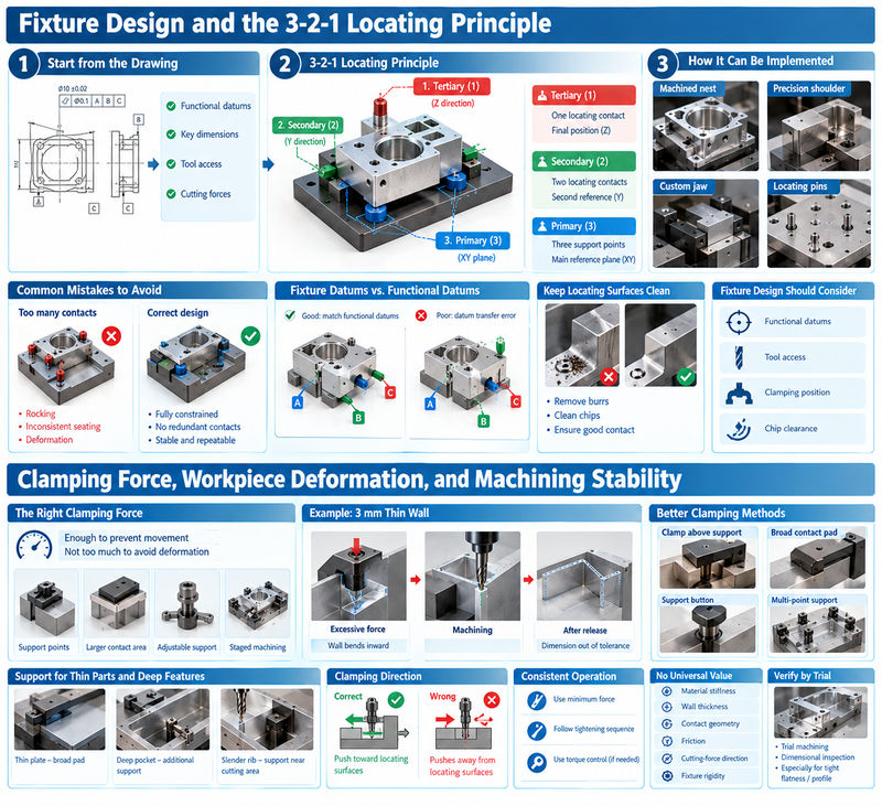
Fixture design begins with the engineering drawing, not with the location of the clamps. The designer must identify the functional datums, critical dimensions, tool access requirements, and cutting forces before deciding how to position the workpiece.
The 3-2-1 locating principle is a common starting point for prismatic parts. It constrains the workpiece’s six degrees of freedom using three primary locating contacts, two secondary contacts, and one tertiary contact. These contacts establish a repeatable reference without unnecessarily restricting the part.
| Locating stage | Typical arrangement | Purpose |
|---|---|---|
| Primary datum | Three support points | Establish the main reference plane |
| Secondary datum | Two locating contacts | Control orientation against a second reference |
| Tertiary datum | One locating contact | Establish the final position along the remaining direction |
The six-contact model is a design principle rather than a requirement to use exactly six separate fixture components. A machined nest, precision shoulder, or custom jaw can perform several locating functions when properly designed.
A common mistake is adding more locating contacts in the belief that more contact automatically improves accuracy. If the part or fixture is not perfectly flat, excessive locating contacts can cause rocking, inconsistent seating, or deformation during clamping. The appropriate design must fully constrain the part without creating harmful redundant constraints.
Fixture datums should also correspond as closely as practical to the functional datums specified in the drawing. Otherwise, datum transfer between setups can introduce additional positioning error.
For precision aluminum housings, locating surfaces should be clean and free of burrs and trapped chips. Even a small chip beneath a locating face can tilt the workpiece and shift a machined feature. Chip-clearance paths, accessible contact surfaces, and repeatable loading procedures should therefore be incorporated into the fixture design.
6. Clamping Force, Workpiece Deformation, and Machining Stability
Clamping force must be sufficient to prevent movement under cutting loads, but excessive force can deform the component. This trade-off is especially important for thin-walled aluminum parts, lightweight brackets, plastic components, and precision housings.
Imagine machining a 3 mm thick aluminum wall. If a screw clamp applies excessive force directly over an unsupported area, the wall may bend inward. The CNC machine can then cut the surface to the programmed dimension while the part is clamped. Once the clamp is released, the wall springs back, leaving the finished dimension or flatness outside the specified tolerance.
The solution is not simply to tighten the clamps further. Better approaches include placing clamps above support points, increasing the contact area, adding adjustable support buttons, or machining the part in stages to balance material removal.
For a thin plate, a broad contact pad may distribute the clamping load more evenly than a small point contact. For a deep pocket or slender rib, additional support near the cutting region may reduce vibration and deflection. Support locations must still permit the tool to reach the required surfaces without collision.
Clamping should push the workpiece toward its locating surfaces rather than away from them. Operators should use a consistent tightening sequence and the minimum force needed for secure machining. Where clamping torque is critical, a controlled torque specification or powered clamping system can improve consistency.
The correct force cannot be determined from a universal value. It depends on material stiffness, wall thickness, contact geometry, friction, cutting-force direction, and fixture rigidity. Trial machining and dimensional inspection after unclamping are particularly valuable for parts with tight flatness or profile requirements.
7. Tool Selection, Cutting Parameters, and Tool Wear
Tool selection and cutting parameters directly influence cycle time, surface finish, dimensional consistency, and tooling costs. Increasing cutting speed or feed may shorten machining time, but aggressive settings can also accelerate wear, cause chatter, or increase heat generation.
A practical machining strategy separates roughing from finishing. Roughing removes the majority of excess material using a suitable material-removal rate, while finishing uses a controlled allowance and stable cutting conditions to achieve the final geometry and surface quality.
For example, when machining an aluminum mounting plate, the roughing operation may remove most of the pocket material. A finishing pass then controls the final wall dimensions and floor surface. Leaving a consistent finishing allowance helps avoid uneven cutting loads that can push the tool away from the programmed path.
Tool wear should be monitored through dimensional trends, surface finish, spindle load, cutting sound, and visible edge damage. A worn end mill may gradually increase burr formation or produce a deteriorating surface before a major dimensional failure occurs.
Tool life should not be evaluated only by how long a cutter remains physically usable. A tool that produces inconsistent dimensions near the end of its life may create inspection failures and expensive rework. In production, replacing tools according to validated tool-life limits can be more economical than waiting for visible breakage.
For harder alloys and demanding operations, tool overhang, holder rigidity, coolant delivery, and chip evacuation require particular attention. Long, flexible tool assemblies and chip recutting can produce vibration, poor finish, and premature tool failure.
8. Fixture Accuracy, Repeatability, and Quality Inspection
Fixture accuracy and repeatability are related but different. Accuracy describes how closely a result matches the intended value, while repeatability describes how consistently the same result is achieved across repeated setups or production cycles.
A fixture may repeatedly locate a component in the same position while still being offset from the required datum. Conversely, a setup may initially align correctly but produce inconsistent results because chips, worn locating pins, variable clamping force, or operator-dependent loading change the workpiece position.
For precision CNC components, inspection should focus on the features most sensitive to setup variation. These may include hole true position, perpendicularity, flatness, parallelism, concentricity-related requirements, and relationships between features machined in separate operations.
| Inspection method | Typical purpose |
|---|---|
| Caliper or micrometer | Check accessible linear dimensions and thickness |
| Dial indicator | Check alignment, runout, and setup variation |
| Height gauge and surface plate | Measure selected heights and geometric relationships |
| Coordinate measuring machine (CMM) | Verify complex geometry and datum-related feature positions |
| Go/no-go gauge | Quickly verify selected production dimensions |
Suppose a mounting bracket requires two holes to remain within a 0.10 mm true position tolerance relative to datum A and datum B. The inspection plan should reproduce the drawing’s datum reference system rather than measure the holes independently from arbitrary edges.
If the first operation establishes a datum face and the second operation drills the holes from that face, the workholding strategy should preserve that reference. Where possible, probing, in-process measurement, and consistent datum transfer can reduce setup-related errors.
A useful quality process also records first-article results, tool changes, fixture maintenance, and recurring dimensional trends. This helps identify whether a defect originates from tool wear, machine alignment, fixture movement, thermal effects, or the workpiece itself.
9. Custom Fixtures for Prototypes and Mass Production
Custom fixtures are not necessary for every CNC machining job. For a one-off prototype or a small batch with simple geometry, a standard vise, modular fixture plate, or machined soft jaws may be the most economical solution.
Dedicated fixtures become more attractive when the part has complex geometry, several critical features, repeated production orders, or a lengthy manual setup. They can reduce alignment time, make part loading more consistent, and support multiple machining operations without repeatedly establishing the entire coordinate system.
Consider an illustrative production run of 500 aluminum brackets. If a standard setup requires four minutes of loading and alignment per part, total setup-related handling time is approximately 33.3 hours. If a dedicated fixture reduces that time to one minute per part, handling time falls to approximately 8.3 hours, saving about 25 hours.
These figures are an example, not a guaranteed production result. The actual benefit depends on fixture design, operator workflow, machining cycle time, and inspection requirements. The cost of fixture design, manufacturing, validation, and maintenance must also be included.
A custom fixture should be evaluated against the complete production process. Engineers need to confirm that it provides tool access, adequate rigidity, safe loading, chip evacuation, and access for inspection. For multi-axis machining, the fixture and workpiece must also be checked for collisions throughout the full toolpath and machine movement.
For recurring orders, modular fixtures or replaceable locating elements may provide a useful balance between dedicated tooling and future flexibility.
10. How Tools and Fixtures Affect CNC Machining Costs and Lead Times
The cost of CNC machining includes more than the machine’s hourly rate and the raw material. Tool consumption, setup time, fixture manufacturing, inspection, scrap, rework, and production interruptions can all affect the final quotation.
A low-cost cutter may appear economical initially, but short tool life can increase tool changes and downtime. A sophisticated fixture may require a larger upfront investment but reduce repeated setup time and lower the risk of inconsistent positioning.
The following example illustrates how fixture investment can affect total manufacturing cost.
| Cost factor | Standard workholding | Dedicated fixture |
|---|---|---|
| Illustrative setup time per part | 4 minutes | 1 minute |
| Quantity | 500 parts | 500 parts |
| Total setup-related time | 33.3 hours | 8.3 hours |
| Potential time saved | — | 25 hours |
If the effective machine-hour cost is $60, saving 25 machine hours would represent $1,500 in potential capacity cost. This is an illustrative calculation: the actual financial saving depends on whether the released machine time can be productively used and whether the dedicated fixture introduces additional costs.
Fixture investment is usually easier to justify for stable, repeat production than for a single prototype. However, a prototype may still require custom workholding if the part is difficult to secure safely or has critical features that cannot be machined reliably using standard equipment.
When requesting a CNC machining quotation, buyers should provide the latest 2D drawings, 3D CAD files, material specifications, critical tolerances, surface-finish requirements, expected order quantities, and any special inspection requirements. These details allow the manufacturer to select suitable tooling, evaluate workholding needs, and estimate realistic production costs and lead times.
Xavier CNC Machining: Tooling and Fixture Solutions for Precision Parts
At Xavier, tooling and fixture selection should be considered part of the complete CNC manufacturing process rather than isolated workshop decisions. The right combination helps establish reliable part location, control cutting loads, improve machining consistency, and reduce unnecessary setup and rework.
Whether you need a prototype aluminum bracket, a stainless steel housing, a precision-machined industrial component, or repeat production of custom metal parts, the manufacturing approach should be matched to the part geometry, material, tolerances, and order volume.
Before production begins, it is worth reviewing the critical datums, thin-wall sections, hole positions, tool access, surface-finish requirements, and inspection method. These details can reveal opportunities to simplify the fixture, reduce unnecessary operations, and make the finished component easier to manufacture consistently.
Contact Xavier to discuss your CNC machining project. Share your drawings, CAD files, material requirements, tolerances, and estimated quantity to request a manufacturing review and quotation for your custom CNC-machined parts.
As an integrated CNC machining manufacturer and trading supplier, Xavier specializes in CNC contract manufacturing and precision machining of a wide range of metal components. We also provide professional surface treatment solutions, including CNC zinc plating surface finishing, CNC anodizing surface finishing, and CNC chemical conversion coating surface finishing, helping customers meet their requirements for corrosion resistance, surface quality, and component performance.
We are a reliable CNC zinc plating manufacturer, offering bulk CNC anodizing services at competitive prices. Contact us to inquire about CNC chemical conversion coating pricing and discuss your project requirements.
Some of the images and text in this article are collected and compiled from the internet. If there is anything inappropriate, please contact us for processing.