
5 Core Topics Covered
- Countersink vs. Counterbore Geometry and Fundamental Differences
- Fastener Selection and Application Scenarios
- CNC Machining Methods, Tools, and Critical Dimensions
- Engineering Drawing Callouts and Hole Specifications
- Design Considerations: Strength, Material Thickness, Cost, and Applications
1. Countersink vs. Counterbore: Geometry and Fundamental Differences
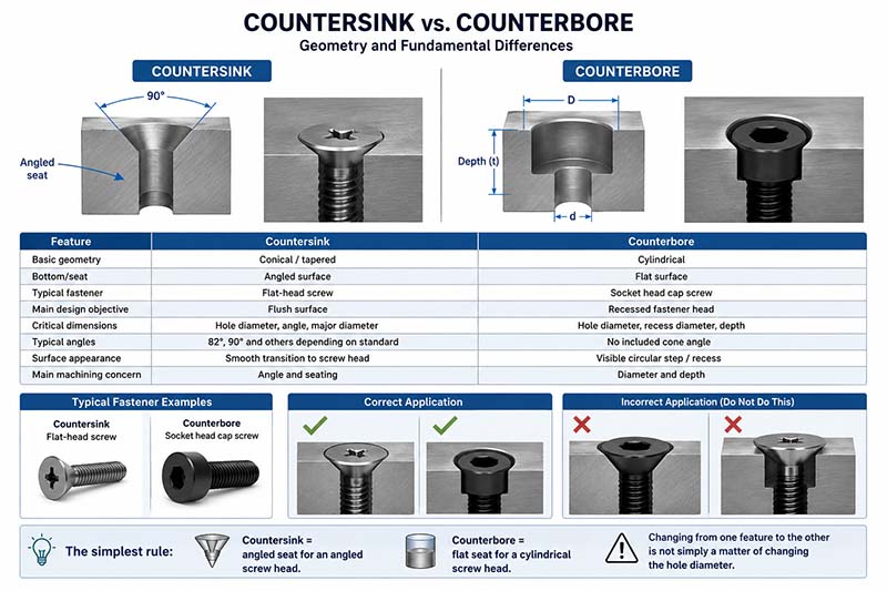
At first glance, a countersink and a counterbore may look like two different ways of enlarging the opening of a drilled hole. In CNC machining, however, they are fundamentally different hole features. The most important distinction is their geometry: a countersink creates a conical recess, while a counterbore creates a cylindrical recess with a flat bottom. This geometric difference determines which fastener can be used, how the fastener head contacts the workpiece, and how the finished assembly behaves.
A countersink is essentially a tapered transition between the main hole and the surface of the workpiece. The tapered wall is designed to match the angled underside of a flat-head screw. When the screw is tightened, its angled head rests against the conical surface, allowing the top of the screw head to become approximately flush with the surrounding material.
A counterbore works differently. Instead of creating an angled seat, the machining operation produces a larger cylindrical cavity above the main hole. The bottom of this cavity is flat, creating a horizontal bearing surface for the underside of a cylindrical fastener head. A socket head cap screw is a typical example.
| Feature | Countersink | Counterbore |
|---|---|---|
| Basic geometry | Conical / tapered | Cylindrical |
| Bottom/seat | Angled surface | Flat surface |
| Typical fastener | Flat-head screw | Socket head cap screw |
| Main design objective | Flush surface | Recessed fastener head |
| Critical dimensions | Hole diameter, angle, major diameter | Hole diameter, recess diameter, depth |
| Typical angles | 82°, 90° and others depending on standard | No included cone angle |
| Surface appearance | Smooth transition to screw head | Visible circular step/recess |
| Main machining concern | Angle and seating | Diameter and depth |
The difference becomes particularly important when the fastener is under load. With a counterbore, the cylindrical screw head can sit on a relatively broad flat surface. With a countersink, the load is transferred through the angled interface between the screw head and the countersunk surface. Therefore, selecting the hole type simply because it “looks right” can create an assembly problem even when the nominal hole diameter is correct.
For example, imagine an aluminum mounting plate that uses an M6 socket head cap screw. A counterbore can provide a flat recess large enough for the cylindrical head of the M6 screw. If the same location is machined as a countersink, the screw head will not have the intended flat seating condition. Conversely, using a counterbore for an M6 flat-head screw leaves the screw head without the correct tapered seat.
The simplest rule is therefore:
Countersink = angled seat for an angled screw head.
Counterbore = flat seat for a cylindrical screw head.
That distinction should be established before machining begins, because changing from one feature to the other is not simply a matter of changing the hole diameter.
2. Fastener Selection: When Should You Use a Countersink or Counterbore?
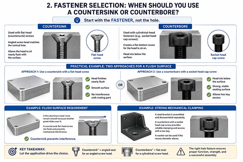
The correct way to select between a countersink and counterbore is to start with the fastener, rather than starting with the hole.
A countersink is normally paired with a flat-head or countersunk screw. The underside of this type of screw has an angled surface that corresponds to the conical wall of the countersunk hole. When the screw is tightened, the two angled surfaces contact each other and allow the head to approach the surface of the workpiece.
A counterbore is normally used with fasteners that have a cylindrical or otherwise flat underside. Socket head cap screws are one of the most common examples. The counterbore creates enough radial clearance for the screw head and enough depth for the head to sit below the part surface.
Consider the following practical example.
Suppose a CNC-machined aluminum housing must be assembled against another component, and no part of the screw head can protrude above the housing surface. The designer has two possible approaches.
If a flat-head screw is selected, a countersink is usually appropriate. The screw head follows the conical surface and can finish nearly flush with the housing. countersink vs counterbore
If a socket head cap screw is selected, a counterbore is usually more appropriate. The cylindrical head drops into the recess while its underside sits against the flat bottom.
The choice also depends on the mechanical requirements of the joint.
Example: Flush Surface Requirement
Consider a thin aluminum cover used on an electronic enclosure. The outer surface may need to remain smooth because another panel slides over it.
A protruding socket head screw could interfere with the mating component. A countersunk flat-head screw may therefore be preferable because the screw head can sit flush with the cover.
In this situation, the countersink is not merely an aesthetic feature. It prevents mechanical interference.
Example: Strong Mechanical Clamping
Now consider a steel machine bracket that is repeatedly assembled and disassembled. The joint may require a socket head cap screw because the fastener must provide reliable clamping force and allow access with a hex key.
A counterbore is often a better choice because the cylindrical screw head has a stable flat seating area. A washer can also be accommodated in some counterbore designs when the geometry allows sufficient diameter.
This is why industrial CNC components often use counterbores around mounting points, while panels, covers, and flush-mounted components frequently use countersinks. The application—not the visual appearance of the CAD model—should determine the feature.
3. CNC Machining Methods, Tools, and Critical Dimensions
From a manufacturing perspective, countersinks and counterbores have different machining requirements even though both are normally produced after or together with the primary hole.
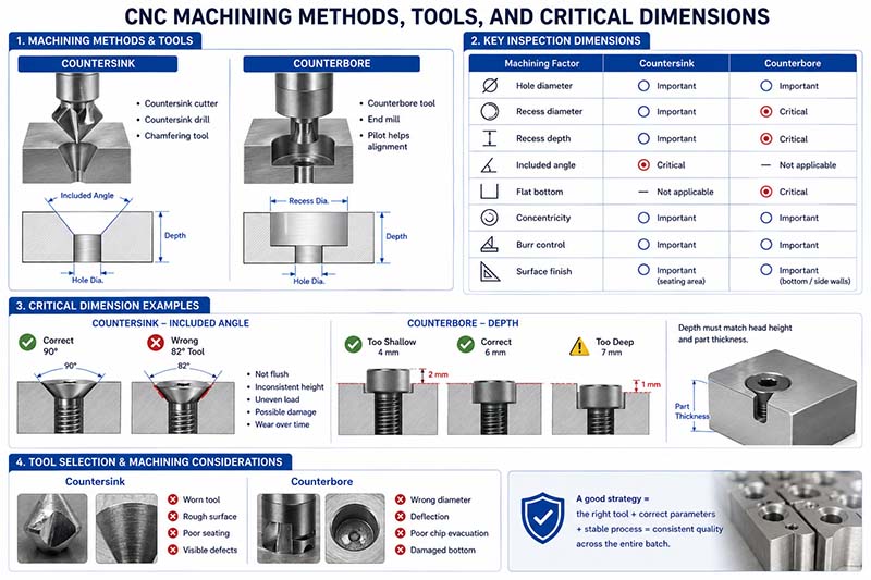
A countersink is commonly produced with a countersink cutter, countersink drill, or suitable chamfering tool. The cutter creates the conical surface at the entrance of the hole. The final geometry depends heavily on the cutter angle and the depth of the cutting operation. countersink vs counterbore
A counterbore requires a cylindrical cutting operation. Depending on the design, a dedicated counterbore tool, end mill, or another suitable cutter can be used. Some counterbore tools use a pilot to help maintain alignment with the existing hole.
The key inspection dimensions are different.
| Machining factor | Countersink | Counterbore |
|---|---|---|
| Hole diameter | Important | Important |
| Recess diameter | Important | Critical |
| Recess depth | Important | Critical |
| Included angle | Critical | Not applicable |
| Flat bottom | Not applicable | Critical |
| Concentricity | Important | Important |
| Burr control | Important | Important |
| Surface finish | Important around seating area | Important on bottom/side walls |
For a countersink, the included angle is particularly important. Common standards use different screw-head angles, so the designer should not assume that every countersunk screw uses the same angle. Search results commonly identify 82° and 90° as widely encountered values, but the correct angle should always be based on the specified fastener standard rather than assumed from appearance.
For example, suppose a drawing specifies a 90° countersink. If a machinist uses an 82° tool, the resulting cone will not properly match the screw head. The screw may still enter the hole, but the contact pattern will be wrong. Instead of obtaining full contact around the intended seating surface, contact may occur near one portion of the cone.
That can cause several problems:
- The screw may not sit completely flush.
- The visible head height may be inconsistent.
- Clamping force may not be distributed as intended.
- The seating surface may be damaged during tightening.
- Repeated assembly may produce additional wear.
Counterbores have a different critical dimension: depth.
For example, imagine a socket head screw with a head height of 6 mm. If the counterbore is only 4 mm deep, approximately 2 mm of the screw head will remain above the surrounding surface, assuming the dimensions are otherwise suitable.
If the counterbore is machined 7 mm deep, the head may sit 1 mm below the surface. That may be acceptable—or it may be undesirable if the remaining material thickness becomes too small.
Therefore, counterbore depth should not be selected independently of the overall part thickness.
Tool Selection Matters More Than It Appears
Tool wear can also affect the finished feature.
A worn countersink cutter may produce a rough or uneven conical surface. Because the countersink directly contacts the screw head, even relatively small machining defects can become visible or affect seating.
Counterbores can develop a different set of problems. An inaccurate cutter diameter can produce insufficient clearance around the screw head. Excessive tool deflection can affect the diameter or depth, while poor chip evacuation can damage the flat bottom.
For precision CNC production, the machining strategy should therefore consider not only whether the machine can produce the geometry, but also how consistently the feature can be reproduced across the entire batch.
4. Engineering Drawing Callouts and How to Specify the Hole Correctly
One of the most common manufacturing problems is not the machining process itself, but an unclear drawing.
A CNC machine shop needs to know exactly what feature is required. Simply writing “recessed hole” or showing a visually similar feature in a 3D model may not be sufficient.
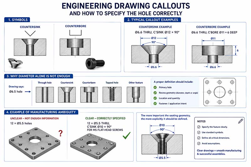
Engineering drawings normally use dedicated symbols and dimensions to distinguish countersinks and counterbores. The countersink symbol is commonly represented as ⌵, while the counterbore symbol is commonly represented as ⌴.
A useful countersink callout might conceptually specify:
Ø6.6 THRU, C’SINK Ø12 × 90°
This tells the machinist that the primary hole is approximately 6.6 mm through the part and that the opening must be countersunk to a 12 mm major diameter with a 90° included angle.
A counterbore specification might conceptually look like:
Ø6.6 THRU, C’BORE Ø11 × 6 DEEP
The first dimension defines the main hole, while the second defines the larger cylindrical recess and its depth.
The exact notation can vary depending on the drawing standard and company drafting practice, but the important principle is that the manufacturing intent should be unambiguous.
Why Diameter Alone Is Not Enough
Suppose a drawing says:
Ø6.5 hole
That does not tell the machinist whether the hole should be:
- a simple through hole,
- a countersunk hole,
- a counterbored hole,
- a tapped hole,
- or another specialized feature.
Likewise, saying “M6 screw hole” may not fully describe the required head clearance.
A proper design definition should establish the primary hole, recess geometry, relevant diameter, depth or angle, and location.
This becomes especially important when a CNC component has dozens or hundreds of holes. A single incorrect feature can create assembly delays even if every other dimension is correct.
Example of a Manufacturing Ambiguity
Imagine a mounting plate with 12 holes for M5 flat-head screws.
If the drawing only specifies:
12 × Ø5.5 holes
the machinist cannot determine whether the screw heads should remain above the surface or be recessed.
If the drawing specifies:
12 × Ø5.5 THRU + countersink for M5 flat-head screws
the manufacturing intent becomes much clearer.
The more important the seating geometry is to assembly, the more explicitly it should be defined on the drawing.
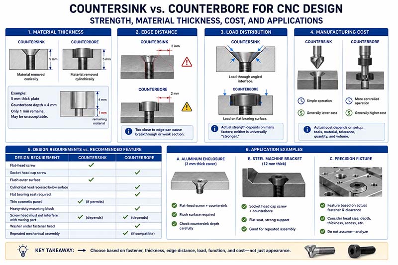
5. Countersink vs. Counterbore for CNC Design: Strength, Material Thickness, Cost, and Applications
Choosing between countersink and counterbore is ultimately a design decision involving more than fastener compatibility.
The first consideration is available material thickness.
A countersink removes material in a conical region that gradually increases toward the surface. A counterbore removes material in a cylindrical pocket with a relatively large diameter and controlled depth. In a thin component, either operation can reduce the remaining wall thickness significantly.
For example, consider a 5 mm thick aluminum plate.
If a counterbore requires a 4 mm deep recess, only 1 mm of material remains beneath the recess before reaching the opposite side. That may be unacceptable if the component carries a significant load.
A countersink can sometimes achieve the desired flush screw-head position while distributing the removed material differently through the thickness. However, the actual suitability still depends on the screw head dimensions, countersink diameter, material, edge distance, and applied load.
The second consideration is edge distance.
Imagine a countersunk hole located only 2 mm from the edge of a thin plate. Because the countersink expands toward the surface, the conical opening may approach or break through the edge. The result can be a sharp edge, insufficient material around the fastener, or even an open-sided recess.
A counterbore can create a similar problem if its diameter is too large, but its cylindrical geometry makes the affected region easier to calculate.
The third consideration is load distribution.
Counterbores provide a flat seating surface for suitable fasteners and can be advantageous where stable head support is important. Countersunk joints rely on the angled interface between the fastener head and the conical seat. The actual strength of either joint depends on fastener material, workpiece material, dimensions, preload, edge distance, joint design, and loading conditions, so it is not accurate to say that one is universally “stronger.”
The fourth consideration is manufacturing cost.
A simple countersink can often be produced with a short machining operation. A counterbore may require a more controlled cylindrical pocketing operation and careful depth control. However, actual cost depends on the machine setup, tool selection, quantity, material, tolerances, and production volume.
| Design requirement | Recommended feature |
|---|---|
| Flat-head screw | Countersink |
| Socket head cap screw | Counterbore |
| Flush outer surface | Countersink |
| Cylindrical head recessed below surface | Counterbore |
| Flat bearing seat required | Counterbore |
| Thin cosmetic panel | Often countersink, if material thickness permits |
| Heavy-duty mounting block | Often counterbore |
| Screw head must not interfere with mating part | Either, depending on fastener |
| Washer under fastener head | Usually counterbore |
| Repeated mechanical assembly | Often counterbore when compatible with the fastener |
Application Example: CNC Aluminum Enclosure
Consider a CNC-machined 6061 aluminum enclosure cover.
The cover is only 3 mm thick and must be mounted to the main housing. The outer surface needs to remain smooth because another component will be positioned directly above it.
A flat-head screw combined with a properly specified countersink may be a logical solution. However, the countersink depth must be checked carefully because removing too much material from a 3 mm cover can create a weak section around the screw.
Application Example: CNC Steel Machine Bracket
Now consider a 12 mm thick steel bracket used to mount a machine assembly. The bracket uses socket head cap screws and must withstand repeated tightening and loosening.
A counterbore may be preferable because the cylindrical screw head can sit below the surface on a flat seat. The recess can also provide clearance around the head and keep the fastener protected from accidental contact.
Application Example: Precision Fixture
CNC fixtures frequently need repeatable positioning and secure clamping. If the screw head must be recessed so that a workpiece can slide across the fixture surface, the feature should be selected based on the actual fastener and required clearance.
In such a case, the designer should not simply specify “counterbore” because it is common in fixtures. The screw head diameter, head height, recess depth, tool access, material thickness, and required surface clearance should all be considered.
Final Recommendation: Choose the Hole Feature Around the Assembly, Not Just the Drawing
The difference between a countersink and counterbore can be summarized in one sentence: a countersink creates an angled seat for a matching fastener head, while a counterbore creates a cylindrical, flat-bottom recess for a fastener with a suitable flat underside.
But for CNC machining, that simple distinction is only the starting point.
A good design process should follow this sequence:
Fastener → required surface condition → hole geometry → material thickness → machining method → inspection requirements.
If the screw must finish flush with the surface and has an angled underside, a countersink is normally the logical solution. If the fastener has a cylindrical head and requires a stable flat bearing surface below the part surface, a counterbore is generally more appropriate.
For custom CNC components, the details matter. Countersink angle, counterbore depth, recess diameter, remaining wall thickness, edge distance, burr control, tool wear, and drawing callouts can all affect whether a finished part assembles correctly.
Xavier provides custom CNC machining services for precision metal and plastic components, including machined holes, countersinks, counterbores, tapped holes, and other complex features. When submitting a drawing or 3D model, specifying the fastener type and the required countersink or counterbore dimensions can help our machining team select the appropriate tooling and manufacturing process from the beginning. For production parts where fit, appearance, repeatability, and dimensional accuracy all matter, working with an experienced CNC machining manufacturer can significantly reduce avoidable assembly and rework problems.
We are an integrated CNC machining manufacturer and trading company specializing in CNC machining services and the custom production of various metal parts. We also support CNC anodizing surface finishing, CNC electroless nickel surface finishing, and CNC chemical conversion coating surface finishing.
We are a CNC anodizing surface finishing manufacturer, providing bulk electroless nickel surface finishing services and offering chemical conversion coating surface finishing pricing. Feel free to contact us for more information.
Some of the images and text in this article are collected and compiled from the internet. If there is anything inappropriate, please contact us for processing.