
Plastic Parts Manufacturer: A Practical Guide to Materials, Manufacturing, Tolerances, and Production
When engineers, product designers, and purchasing teams look for a plastic parts manufacturer, they are usually looking for more than a supplier that can simply produce a plastic component. The right manufacturing partner needs to understand material behavior, part geometry, machining or molding limitations, dimensional tolerances, surface requirements, production volume, and final application.
A plastic part that looks simple on a CAD model can become difficult to manufacture once requirements such as ±0.05 mm tolerances, thin walls, threaded holes, snap-fit features, chemical resistance, high-temperature performance, or cosmetic surfaces are introduced.
Professional plastic parts manufacturing therefore starts before production. Material selection, manufacturing-process selection, design review, tooling strategy, and inspection requirements should all be considered together.
The five areas below explain the most important factors engineers should evaluate when developing custom plastic parts.
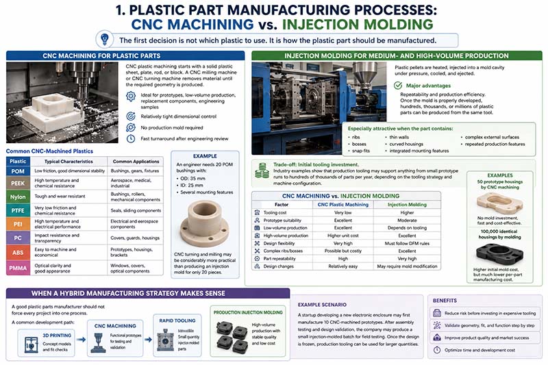
1. Plastic Part Manufacturing Processes: CNC Machining vs. Injection Molding
The first decision is not which plastic to use. It is how the plastic part should be manufactured.
For custom plastic components, CNC machining and injection molding are two of the most important manufacturing methods. They can produce similar-looking components, but their economics, design requirements, tolerances, and suitable production volumes are very different.
CNC Machining for Plastic Parts
CNC plastic machining starts with a solid plastic sheet, plate, rod, or block. A CNC milling machine or CNC turning machine removes material until the required geometry is produced.
This makes CNC machining particularly useful for prototypes, low-volume production, replacement components, engineering samples, and parts requiring relatively tight dimensional control.
Common CNC-machined plastics include:
| Plastic | Typical Characteristics | Common Applications |
|---|---|---|
| POM | Low friction, good dimensional stability | Bushings, gears, fixtures |
| PEEK | High temperature and chemical resistance | Aerospace, medical, industrial |
| Nylon | Tough and wear resistant | Bushings, rollers, mechanical components |
| PTFE | Very low friction and chemical resistance | Seals, sliding components |
| PEI | High temperature and electrical performance | Electrical and aerospace components |
| PC | Impact resistance and transparency | Covers, guards, housings |
| ABS | Easy to machine and economical | Prototypes, housings, brackets |
| PMMA | Optical clarity and good appearance | Windows, covers, optical components |
A major advantage is that no production mold is required. A customer can send a STEP file and 2D drawing, select the material, specify tolerances, and begin manufacturing after engineering review.
For example, suppose an engineer needs 20 POM bushings with an outside diameter of 35 mm, an inside diameter of 25 mm, and several mounting features. CNC turning and milling may be considerably more practical than producing an injection mold for only 20 pieces.
Injection Molding for Medium- and High-Volume Production
Injection molding works differently. Plastic pellets are heated, injected into a mold cavity under pressure, cooled, and ejected.
The major advantage is repeatability and production efficiency. Once the mold is properly developed, hundreds, thousands, or millions of plastic parts can be produced from the same tool.
Injection molding is especially attractive when the part contains:
- ribs
- bosses
- snap-fits
- thin walls
- curved housings
- integrated mounting features
- complex external surfaces
- repeated production features
Industry examples show that production tooling may support anything from small prototype runs to hundreds of thousands of parts per year, depending on the tooling strategy and machine configuration.
The trade-off is the initial tooling investment.
A useful comparison is:
| Factor | CNC Plastic Machining | Injection Molding |
|---|---|---|
| Tooling cost | Very low | Higher |
| Prototype suitability | Excellent | Moderate |
| Low-volume production | Excellent | Depends on tooling |
| High-volume production | Higher unit cost | Excellent |
| Design flexibility | Very high | Must follow DFM rules |
| Complex ribs/bosses | Possible but costly | Excellent |
| Part repeatability | High | Very high |
| Design changes | Relatively easy | May require mold modification |
For example, producing 50 prototype housings by CNC machining may be sensible because there is no mold investment. Producing 100,000 identical housings is a completely different situation. Even though the initial mold costs more, the per-part manufacturing cost can become substantially lower.
When a Hybrid Manufacturing Strategy Makes Sense
A good plastic parts manufacturer should not force every project into one process.
A common development path is:
3D printing → CNC machining → rapid tooling → production injection molding
For example, a startup developing a new electronic enclosure may first manufacture 10 CNC-machined prototypes. After assembly testing and design validation, the company may produce a small injection-molded batch for field testing. Once the design is frozen, production tooling can be used for larger quantities.
This approach reduces the risk of investing in expensive tooling before the product geometry has been fully validated.
2. Plastic Material Selection for Custom Parts
Material selection is one of the most important engineering decisions in plastic parts manufacturing.
Two plastics can look almost identical but behave completely differently under heat, load, moisture, chemicals, and machining forces.
Commodity Plastics vs. Engineering Plastics
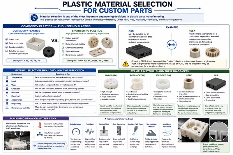
Commodity plastics such as ABS, PP, PE, and PS are often selected when cost, manufacturability, and general-purpose performance are the primary concerns.
Engineering plastics such as POM, PA, PC, PEEK, PEI, and PTFE are selected when the component must satisfy more demanding mechanical, thermal, electrical, or chemical requirements.
For example:
ABS may be suitable for an electronic enclosure that operates at normal ambient temperatures.
PEEK may be more appropriate for a component exposed to elevated temperature, aggressive chemicals, or demanding mechanical conditions.
Choosing PEEK simply because it is a “better” plastic would not necessarily be good engineering. PEEK is significantly more expensive than ABS or POM, and its properties may be unnecessary for a simple enclosure.
Material Selection Should Follow the Application
A practical material-selection process should answer several questions:
| Requirement | Questions to Ask |
|---|---|
| Temperature | What are the continuous and peak operating temperatures? |
| Load | Is the part subjected to compression, tension, bending, or impact? |
| Wear | Will another component slide or rotate against it? |
| Chemicals | Will the part contact oil, solvents, acids, or cleaning agents? |
| Moisture | Will the component absorb water or operate outdoors? |
| Electrical | Is electrical insulation required? |
| Appearance | Does the part require transparency, gloss, texture, or a specific color? |
| Regulatory | Are UL, FDA, RoHS, REACH, or other requirements applicable? |
| Dimensional stability | Must the part maintain tight dimensions over temperature and humidity changes? |
For example, nylon is widely used for mechanical components because of its strength and wear resistance. However, nylon can absorb moisture, which can influence dimensions and mechanical behavior.
POM is often attractive for precision mechanical components because of its low friction and good dimensional stability.
PTFE offers exceptional chemical resistance and very low friction, but its relatively high thermal expansion and softness can make tight dimensional control more challenging.
PEEK offers excellent overall engineering performance but may be unnecessarily expensive for a low-load consumer component.
Machining Behavior Matters Too
The material’s machining behavior must also be considered.
Plastic does not behave like aluminum or steel during CNC machining. Excessive cutting heat can soften the material, while insufficient support can cause thin sections to deflect.
A manufacturer may therefore adjust:
- spindle speed
- feed rate
- depth of cut
- tool geometry
- coolant or air flow
- workholding method
- machining sequence
For thin-wall plastic parts, machining strategy can be just as important as material selection.
3. Design for Manufacturability: Wall Thickness, Ribs, Bosses, Draft, and Radii
A professional plastic parts manufacturer should review the CAD model before production rather than simply manufacturing whatever geometry is supplied.
This is where Design for Manufacturability (DFM) becomes important.
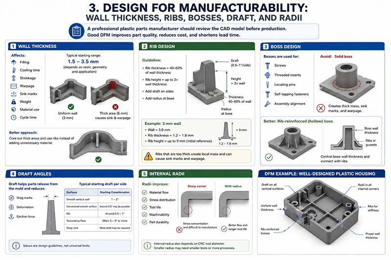
Injection-molded parts are particularly sensitive to wall thickness, draft angle, ribs, bosses, gate location, and cooling behavior. Current engineering guidance commonly recommends maintaining relatively uniform walls and using ribs or gussets to add stiffness instead of creating unnecessarily thick sections.
Wall Thickness
Wall thickness influences:
- filling
- cooling time
- shrinkage
- warpage
- sink marks
- part weight
- material consumption
- cycle time
For many common injection-molded engineering plastics, a nominal wall around 1.5–3.5 mm is a practical starting range, but the appropriate value depends strongly on resin, flow length, geometry, and application.
Consider a housing designed with a 3 mm nominal wall.
If one area suddenly becomes 6 mm thick, that region contains twice the material thickness and will cool differently from the surrounding wall. This can create sink marks or warpage.
Instead of simply adding material, an engineer may core out the thick area and use ribs.
Rib Design
Ribs increase stiffness without requiring the entire wall to become thicker.
A commonly used starting guideline is to keep rib thickness around 40–60% of the adjacent nominal wall thickness. Rib height is often reviewed around three times the wall thickness, with draft and a radius added at the rib base.
For a 3 mm wall:
- Nominal wall = 3.0 mm
- Rib thickness ≈ 1.2–1.8 mm
- Rib height ≈ up to about 9 mm as an initial design reference
- Rib base should have a radius
- Rib sidewalls should include draft
The exact values should still be validated against the selected resin and mold geometry.
The reason is simple: a rib that is too thick becomes a local mass of plastic. During cooling, that thick area can shrink differently from the surrounding wall and create a visible sink mark.
Boss Design
Bosses are commonly used for:
- screws
- threaded inserts
- locating pins
- self-tapping fasteners
- assembly alignment
A poorly designed boss can create both structural and cosmetic problems.
Instead of making the boss a solid cylinder attached to a flat wall, manufacturers commonly use a hollow boss with supporting ribs or gussets.
For example, if a 3 mm housing contains a boss for an M4 screw, the boss should not simply become a large solid mass several millimeters thicker than the surrounding wall.
The better approach is to control boss-wall thickness and connect the boss to the surrounding structure with ribs.
Draft Angles
Draft is the taper applied to surfaces in the mold-opening direction.
Without enough draft, the molded part can stick to the tool during ejection, producing drag marks, deformation, or excessive ejection force.
For many untextured surfaces, 1–2° of draft per side is a practical starting point. Textured surfaces usually require more draft because the texture increases contact with the mold surface.
For example:
| Surface | Typical Starting Consideration |
|---|---|
| Smooth vertical wall | 1–2° |
| Constrained smooth surface | Around 0.5° may be possible |
| Rib | Around 0.5–1° per side |
| Textured surface | Often 3–5° or more |
| Deep core | More draft may be required |
These values are design guidelines rather than universal manufacturing limits.
Internal Radii
Sharp internal corners can create stress concentrations and manufacturing difficulties.
Adding a radius improves:
- material flow
- stress distribution
- tool life
- machinability
- part durability
For CNC machining, the internal corner radius is also affected by the cutting-tool diameter. A smaller radius may require a smaller end mill, additional machining passes, or EDM in some tooling applications.
This is why a plastic parts manufacturer should review internal geometry before quoting.
4. Plastic Part Tolerances, Dimensional Stability, and Quality Control
One of the biggest mistakes in plastic part manufacturing is treating every dimension as if it can be held to the same tolerance.
Plastic is sensitive to temperature, moisture, shrinkage, internal stress, machining conditions, and material grade.
CNC Plastic Machining Tolerances
CNC machining can provide relatively tight tolerances, but the realistic tolerance depends on:
- material
- part size
- wall thickness
- geometry
- machine capability
- temperature
- inspection method
- machining strategy
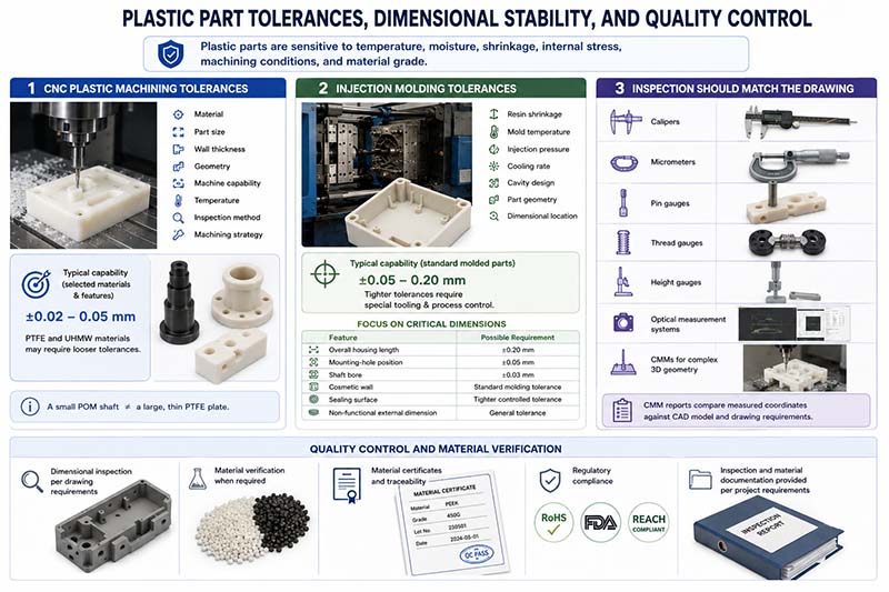
For example, engineering references for CNC plastics commonly discuss approximate capability ranges around ±0.02–0.05 mm for selected materials and features, while PTFE and UHMW materials can require looser tolerances because of their dimensional behavior.
A small POM shaft may therefore be treated very differently from a large, thin PTFE plate.
Injection Molding Tolerances
Injection molding tolerances are influenced by:
- resin shrinkage
- mold temperature
- injection pressure
- cooling rate
- cavity design
- part geometry
- dimensional location
Published manufacturing capabilities commonly place standard molded-part tolerances around approximately ±0.05–0.20 mm, depending on the feature and process, while tighter tolerances may require special tooling and process control.
Therefore, writing ±0.02 mm on every dimension of an injection-molded housing is not a practical specification strategy.
Instead, engineers should identify critical dimensions.
For example:
| Feature | Possible Requirement |
|---|---|
| Overall housing length | ±0.20 mm |
| Mounting-hole position | ±0.05 mm |
| Shaft bore | ±0.03 mm |
| Cosmetic wall | Standard molding tolerance |
| Sealing surface | Tighter controlled tolerance |
| Non-functional external dimension | General tolerance |
This approach tells the manufacturer where precision actually matters.
Inspection Should Match the Drawing
A professional manufacturer may use different inspection tools for different features:
- calipers for general dimensions
- micrometers for precision external dimensions
- pin gauges for holes
- thread gauges for threaded features
- height gauges for positional measurements
- optical measurement systems for profiles
- CMMs for complex three-dimensional geometry
For a precision plastic component, a CMM inspection report can compare measured coordinates against the original CAD model and drawing requirements.
Quality control should also include material verification where necessary. Some plastic applications require material certificates, traceability, or regulatory documentation. Manufacturing suppliers commonly provide inspection and material documentation depending on project requirements.
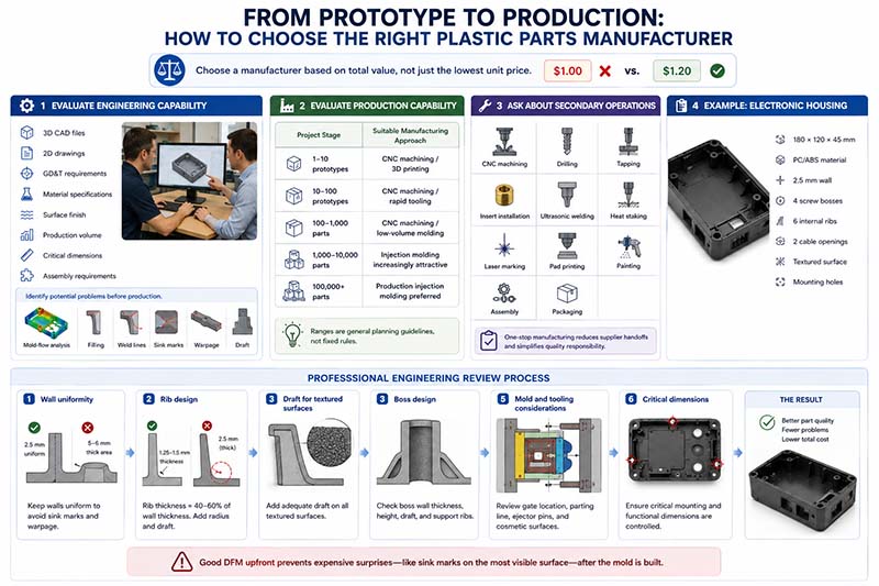
5. From Prototype to Production: How to Choose the Right Plastic Parts Manufacturer
Selecting a plastic parts manufacturer should not be based solely on the lowest unit price.
A supplier quoting $1.00 per part may ultimately be more expensive than a supplier quoting $1.20 if the cheaper supplier produces excessive scrap, has unstable dimensions, or requires repeated tooling modifications.
Evaluate Engineering Capability
A capable manufacturer should be able to review:
- 3D CAD files
- 2D engineering drawings
- GD&T requirements
- material specifications
- surface-finish requirements
- production volume
- critical dimensions
- assembly requirements
The manufacturer should also be willing to identify potential manufacturing problems before production.
For injection molding, this may involve DFM review and mold-flow analysis. Modern DFM workflows can identify potential problems involving filling, weld lines, sink marks, warpage, draft, and tooling before the mold is manufactured.
Evaluate Production Capability
A plastic parts manufacturer should ideally support the production stage that matches the customer’s requirements.
For example:
| Project Stage | Suitable Manufacturing Approach |
|---|---|
| 1–10 prototypes | CNC machining / 3D printing |
| 10–100 prototypes | CNC machining / rapid tooling |
| 100–1,000 parts | CNC machining / low-volume molding |
| 1,000–10,000 parts | Injection molding becomes increasingly attractive |
| 100,000+ parts | Production injection molding is often preferred |
These are general planning ranges, not fixed rules. Part geometry, material, mold cost, cycle time, and unit price can change the economic break-even point significantly.
Ask About Secondary Operations
The molded or machined component may not be the finished product.
Depending on the application, a plastic parts manufacturer may need to provide:
- CNC secondary machining
- drilling
- tapping
- reaming
- insert installation
- ultrasonic welding
- heat staking
- laser marking
- pad printing
- painting
- assembly
- packaging
For example, an injection-molded housing may require brass threaded inserts before it can be assembled with the electronic PCB.
A one-stop supplier can reduce the number of supplier handoffs and simplify quality responsibility.
Example: Manufacturing a Custom Electronic Housing
Consider an electronic device housing measuring approximately 180 × 120 × 45 mm.
The initial design uses:
- PC/ABS material
- 2.5 mm nominal wall
- four screw bosses
- six internal ribs
- two cable openings
- textured external surface
- several mounting holes
A professional engineering review would first check wall uniformity.
The 2.5 mm wall should remain reasonably consistent instead of becoming 5–6 mm around the bosses.
Next, the ribs would be reviewed. If a rib is 2.5 mm thick, it is already close to the full wall thickness and may create a sink-mark risk. Reducing the rib to approximately 1.25–1.5 mm and adding an appropriate radius and draft may provide better molding behavior.
The textured external surfaces would then require additional draft.
The four bosses would be reviewed for wall thickness, height, draft, and support ribs.
Finally, the manufacturer would evaluate gate location, parting line position, ejector-pin locations, cosmetic surfaces, and critical mounting dimensions.
This process can prevent a common and expensive scenario: discovering after the mold is manufactured that the housing has sink marks directly on its most visible surface.
Why a Professional Plastic Parts Manufacturer Should Be Involved Early
The earlier the manufacturer becomes involved, the easier it is to solve manufacturing problems.
Changing a CAD model before tooling is relatively inexpensive.
Changing the steel mold after T1 samples have revealed a design problem is much more expensive.
The same principle applies to CNC machining. A 1 mm internal corner radius may be easy to machine with a suitable tool, while a very small internal radius may require a smaller cutter, slower machining, more passes, or a different manufacturing strategy.
Therefore, manufacturing knowledge should influence the design before the production order is released.
Common Mistakes When Ordering Custom Plastic Parts
Several mistakes repeatedly cause delays and unexpected costs.
Choosing Material by Price Alone
The cheapest plastic is not necessarily the cheapest solution.
A low-cost material that warps, wears rapidly, absorbs moisture, or fails under temperature can generate much higher lifecycle costs.
Applying Tight Tolerances Everywhere
Not every feature needs ±0.02 mm.
Unnecessary tight tolerances increase machining time, inspection requirements, rejection risk, and manufacturing cost.
Ignoring Wall Thickness
Thick sections in injection molding can create sink marks, voids, and warpage.
Designing Without Draft
A beautiful CAD model may still be difficult or impossible to eject efficiently from an injection mold.
Waiting Until Production to Discuss Quality
Inspection requirements should be defined before manufacturing starts, especially for critical dimensions and functional interfaces.
Final Thoughts: Choosing the Right Plastic Parts Manufacturer
A reliable plastic parts manufacturer should be able to connect material selection, manufacturing process, DFM, tolerances, inspection, and production volume into one practical manufacturing plan.
For prototypes and low-volume precision components, CNC machining can provide excellent flexibility without the investment required for production tooling. For larger production volumes, injection molding can deliver high repeatability and competitive unit costs once the tooling has been properly developed.
Material selection should be based on the actual operating environment rather than simply choosing the strongest or most expensive plastic. At the same time, part geometry should be designed around real manufacturing constraints such as wall thickness, draft, ribs, bosses, internal radii, shrinkage, and cooling.
For companies that need custom plastic components, Xavier can provide a practical manufacturing approach from engineering review through CNC plastic machining, precision component production, and customized manufacturing support. By combining material knowledge, CNC machining expertise, manufacturing experience, and quality control, Xavier helps customers turn plastic part designs into manufacturable components rather than simply producing whatever appears in a CAD file.
For a new plastic component, the best starting point is to provide the 3D CAD model, 2D drawing, material requirement, estimated quantity, critical tolerances, and application environment. With these details, the manufacturing process can be evaluated before production, helping reduce unnecessary tooling costs, machining problems, dimensional variation, and redesigns.
We are an integrated CNC machining manufacturer focused on CNC contract manufacturing and the production of custom metal parts. Our capabilities include CNC passivation surface finishing, CNC chemical conversion coating surface finishing, and CNC electrogalvanizing surface finishing, providing reliable finishing solutions for a wide range of machined components.
We are a trusted CNC passivation surface finishing manufacturer, offering CNC chemical conversion coating surface finishing services for bulk orders. Contact us for CNC electrogalvanizing surface finishing pricing and let us know your machining requirements.
Some of the images and text in this article are collected and compiled from the internet. If there is anything inappropriate, please contact us for processing.