
Manufacturing precision is not simply about making a part “as accurate as possible.” In real-world production, precision means controlling dimensional variation, geometry, surface quality, and repeatability so that a component consistently performs its intended function.
For CNC machining, precision becomes especially important when a component must fit with another part, maintain a controlled clearance, seal against a mating surface, rotate around a bearing, or maintain alignment within an assembly. A part can look perfect visually and still fail because a hole is slightly misplaced, two surfaces are not parallel, or a shaft diameter varies outside its functional tolerance.
Based on current machining and precision-manufacturing discussions, five closely related topics are particularly important when evaluating manufacturing precision:
- Manufacturing Precision: Accuracy, Precision, and Repeatability
- Machining Tolerances and How Tight Tolerances Affect Cost
- GD&T and Functional Control of Machined Features
- Process Control, Material, Tooling, and Thermal Stability
- Inspection, CMM Measurement, and Quality Verification
1. Manufacturing Precision: Accuracy, Precision, and Repeatability
Precision manufacturing starts with understanding three terms that are often incorrectly used as if they mean the same thing: accuracy, precision, and repeatability.
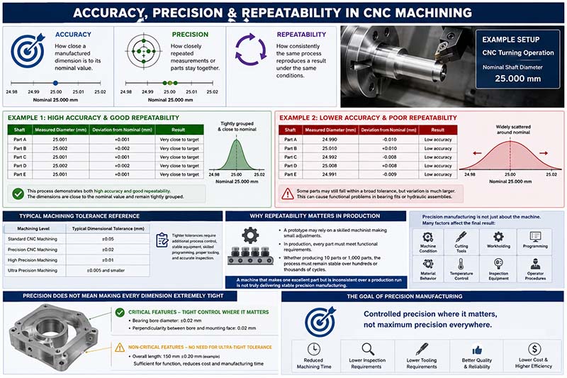
Accuracy describes how close a manufactured dimension is to its nominal value. Precision describes how closely repeated measurements or manufactured parts stay together. Repeatability describes how consistently the same manufacturing process can reproduce a result under the same conditions.
For example, imagine a CNC turning operation designed to produce a shaft with a nominal diameter of 25.000 mm.
| Shaft | Measured Diameter | Result |
|---|---|---|
| Part A | 25.001 mm | Very close to target |
| Part B | 25.002 mm | Very close to target |
| Part C | 25.001 mm | Very close to target |
| Part D | 25.002 mm | Very close to target |
| Part E | 25.001 mm | Very close to target |
This process demonstrates both high accuracy and good repeatability. The dimensions are close to the nominal value and remain tightly grouped.
Now consider another process:
| Shaft | Measured Diameter | Result |
| Part A | 24.990 mm | -0.010 mm |
| Part B | 25.010 mm | +0.010 mm |
| Part C | 24.992 mm | -0.008 mm |
| Part D | 25.008 mm | +0.008 mm |
| Part E | 24.991 mm | -0.009 mm |
Some of these parts may still fall within a relatively broad tolerance, but the variation is much larger. If the component is used in a bearing fit or hydraulic assembly, this variation can become a functional problem.
Current precision-machining references commonly distinguish standard CNC machining from tighter precision machining, with ±0.05 mm often used as a general machining reference while tighter requirements such as ±0.02 mm, ±0.01 mm, or even smaller may require additional process control and inspection.
Why repeatability matters in production
A prototype can sometimes be produced successfully with a highly skilled machinist making small adjustments during machining. Production manufacturing is different.
If 10 parts are required, every part needs to meet the functional requirements. If 1,000 parts are required, the manufacturing process must remain stable over hundreds or thousands of machining cycles.
This is why precision manufacturing is not simply a matter of using a high-end CNC machine. Machine condition, cutting tools, workholding, programming, material behavior, temperature, inspection equipment, and operator procedures all contribute to the final result.
A machine that produces one excellent part but produces inconsistent results over a production run is not truly delivering stable precision manufacturing.
Precision does not mean making every dimension extremely tight
A common engineering mistake is specifying extremely tight tolerances on every dimension.
Suppose a machined aluminum housing has an overall length of 150 mm. The housing may require ±0.02 mm on a bearing bore and a controlled perpendicularity relationship between the bore and mounting face. However, its external non-functional length may not need a ±0.005 mm tolerance.
Applying an ultra-tight tolerance to every feature increases machining time, inspection requirements, tooling requirements, and rejection risk without necessarily improving product performance.
The goal of precision manufacturing should therefore be controlled precision where it matters, rather than maximum precision everywhere.
2. Machining Tolerances and How Tight Tolerances Affect Cost
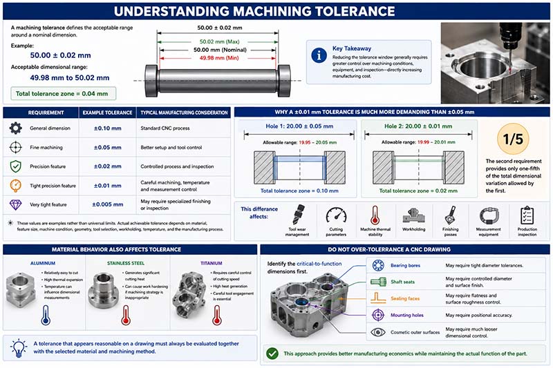
A machining tolerance defines the acceptable range around a nominal dimension.
For example, if a drawing specifies:
50.00 ± 0.02 mm
the acceptable dimensional range is:
49.98 mm to 50.02 mm
The total tolerance zone is therefore 0.04 mm.
This simple concept has a major effect on manufacturing cost because reducing the tolerance window generally requires greater control over machining conditions and inspection.
| Requirement | Example Tolerance | Typical Manufacturing Consideration |
| General dimension | ±0.10 mm | Standard CNC process |
| Fine machining | ±0.05 mm | Better setup and tool control |
| Precision feature | ±0.02 mm | Controlled process and inspection |
| Tight precision feature | ±0.01 mm | Careful machining, temperature and measurement control |
| Very tight feature | ±0.005 mm | May require specialized finishing or inspection |
These values are examples rather than universal limits. Actual achievable tolerance depends on material, feature size, machine condition, geometry, tool selection, workholding, temperature, and the manufacturing process. Published CNC tolerance guides similarly show that tighter tolerances require increasingly careful machining and inspection.
Why a ±0.01 mm tolerance is much more demanding than ±0.05 mm
Consider two holes with the same nominal diameter.
The first hole is specified as:
20.00 ± 0.05 mm
Its allowable range is 19.95–20.05 mm, giving a total tolerance zone of 0.10 mm.
The second hole is:
20.00 ± 0.01 mm
Its allowable range is 19.99–20.01 mm, giving a total tolerance zone of only 0.02 mm.
The second requirement provides only one-fifth of the total dimensional variation allowed by the first.
That difference affects tool wear management, cutting parameters, machine thermal stability, workholding, finishing passes, measurement equipment, and production inspection.
Material behavior also affects tolerance
Different materials react differently during machining.
Aluminum is relatively easy to cut, but its high thermal expansion means that temperature can influence dimensional measurements. Stainless steel can generate significant cutting heat and work hardening if the machining strategy is inappropriate. Titanium requires careful control of cutting speed, heat generation, and tool engagement.
For this reason, a tolerance that appears reasonable on a drawing must always be evaluated together with the selected material and machining method.
Do not over-tolerance a CNC drawing
A better approach is to identify the critical-to-function dimensions first.
For example:
- Bearing bores may require tight diameter tolerances.
- Shaft seats may require controlled diameter and surface finish.
- Sealing faces may require flatness and surface roughness control.
- Mounting holes may require positional accuracy.
- Cosmetic outer surfaces may require much looser dimensional control.
This approach provides better manufacturing economics while maintaining the actual function of the part. Modern tolerance guidance similarly emphasizes applying tight tolerances only where function requires them rather than unnecessarily controlling every dimension.
3. GD&T and Functional Control of Machined Features
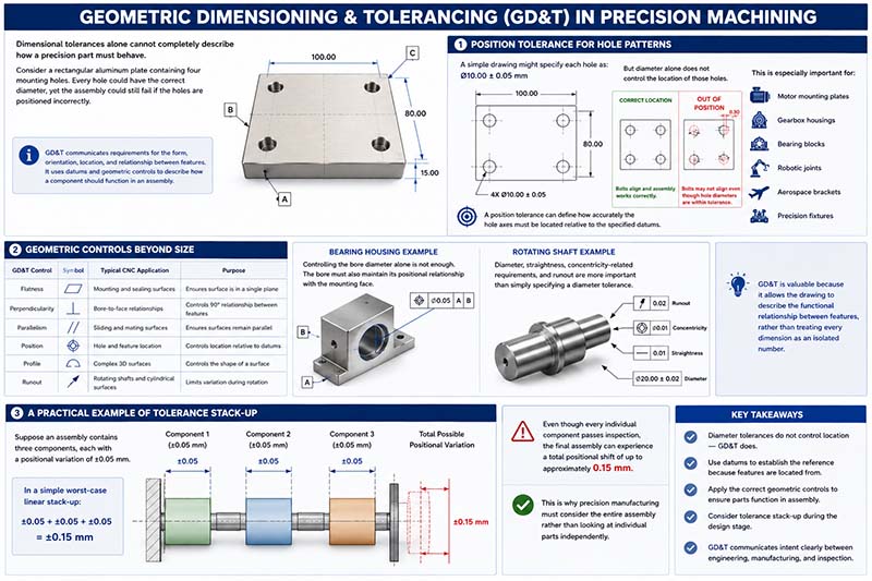
Dimensional tolerances alone cannot completely describe how a precision part must behave.
Consider a rectangular aluminum plate containing four mounting holes. Every hole could have the correct diameter, yet the assembly could still fail if the holes are positioned incorrectly.
This is where Geometric Dimensioning and Tolerancing (GD&T) becomes important.
GD&T communicates requirements for the form, orientation, location, and relationship between features. It uses datums and geometric controls to describe how a component should function in an assembly.
Position tolerance for hole patterns
Imagine a mounting plate with four holes designed to accept four bolts.
A simple drawing might specify each hole as:
Ø10.00 ± 0.05 mm
But diameter alone does not control the location of those holes.
If the holes are 0.30 mm away from their intended positions, the bolts may not align with the mating component even though every hole diameter is acceptable.
A position tolerance can define how accurately the hole axes must be located relative to the specified datums.
This is especially important for:
- Motor mounting plates
- Gearbox housings
- Bearing blocks
- Robotic joints
- Aerospace brackets
- Precision fixtures
Flatness, perpendicularity, parallelism, and runout
Different precision features require different geometric controls.
| GD&T Control | Typical CNC Application |
| Flatness | Mounting and sealing surfaces |
| Perpendicularity | Bore-to-face relationships |
| Parallelism | Sliding and mating surfaces |
| Position | Hole and feature location |
| Profile | Complex 3D surfaces |
| Runout | Rotating shafts and cylindrical surfaces |
For a bearing housing, for example, simply controlling the bore diameter may not be sufficient. The bore may also need to maintain its positional relationship with the mounting face.
For a rotating shaft, diameter, straightness, concentricity-related requirements, and runout can become more important than simply specifying a diameter tolerance.
GD&T is particularly valuable because it allows the drawing to describe the functional relationship between features, rather than treating every dimension as an isolated number.
A practical example of tolerance stack-up
Suppose an assembly contains three components, each with a positional variation of ±0.05 mm.
In a simple worst-case linear stack-up:
±0.05 + ±0.05 + ±0.05 = ±0.15 mm
Even though every individual component passes inspection, the final assembly can experience a total positional shift of up to approximately 0.15 mm.
This is why precision manufacturing must consider the entire assembly rather than looking at individual parts independently.
4. Process Control, Material, Tooling, and Thermal Stability
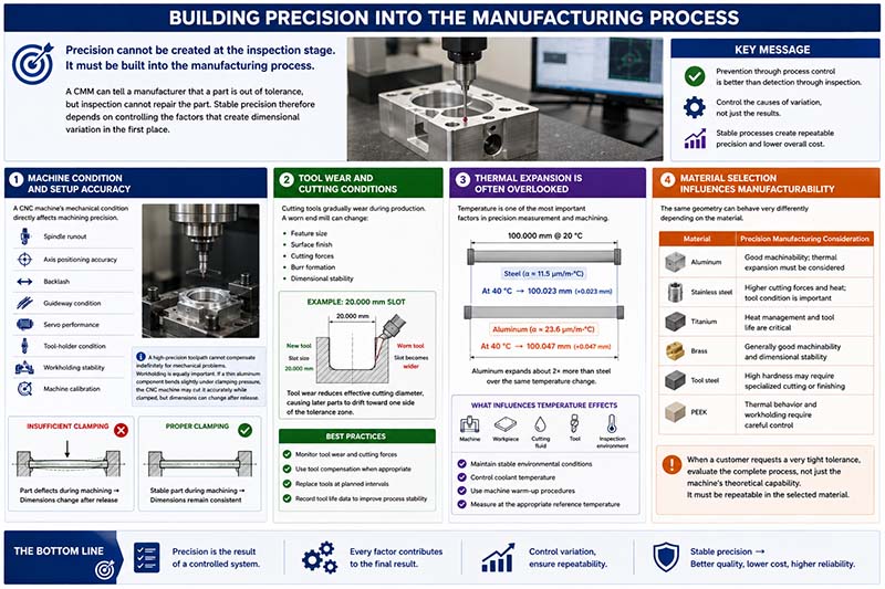
Precision cannot be created at the inspection stage. It must be built into the manufacturing process.
A CMM can tell a manufacturer that a part is out of tolerance, but inspection cannot repair the part. Stable precision therefore depends on controlling the factors that create dimensional variation in the first place.
Machine condition and setup accuracy
A CNC machine’s mechanical condition directly affects machining precision.
Important factors include:
- Spindle runout
- Axis positioning accuracy
- Backlash
- Guideway condition
- Servo performance
- Tool-holder condition
- Workholding stability
- Machine calibration
A high-precision toolpath cannot compensate indefinitely for mechanical problems.
Workholding is equally important. If a thin aluminum component bends slightly under clamping pressure, the CNC machine may cut the component accurately in its clamped condition, but the dimensions can change after the part is released.
Tool wear and cutting conditions
Cutting tools gradually wear during production.
A worn end mill can change:
- Feature size
- Surface finish
- Cutting forces
- Burr formation
- Dimensional stability
For example, if an end mill is producing a 20.000 mm slot at the beginning of a production run and tool wear gradually reduces the effective cutting diameter, later parts may move toward one side of the tolerance zone.
Precision machining therefore requires tool-life monitoring and, where appropriate, tool compensation or scheduled tool replacement.
Thermal expansion is often overlooked
Temperature is one of the most important factors in precision measurement and machining.
A steel component measuring exactly 100.000 mm at one temperature will not necessarily have exactly the same physical length at another temperature. Aluminum is particularly sensitive to temperature changes because its coefficient of thermal expansion is significantly higher than that of steel.
This becomes important when machining a large aluminum component to a tight tolerance. The machine, workpiece, cutting fluid, tool, and inspection environment can all influence the final measurement.
Precision machining therefore benefits from stable environmental conditions, consistent coolant temperature, controlled warm-up procedures, and measurement at an appropriate reference temperature.
Material selection influences manufacturability
The same geometry can behave very differently depending on the material.
| Material | Precision Manufacturing Consideration |
| Aluminum | Good machinability; thermal expansion must be considered |
| Stainless steel | Higher cutting forces and heat; tool condition is important |
| Titanium | Heat management and tool life are critical |
| Brass | Generally good machinability and dimensional stability |
| Tool steel | High hardness may require specialized cutting or finishing |
| PEEK | Thermal behavior and workholding require careful control |
Therefore, when a customer requests a very tight tolerance, the manufacturer should evaluate not only whether the CNC machine can theoretically achieve it, but whether the complete process can repeatedly achieve it in the selected material.
5. Inspection, CMM Measurement, and Quality Verification
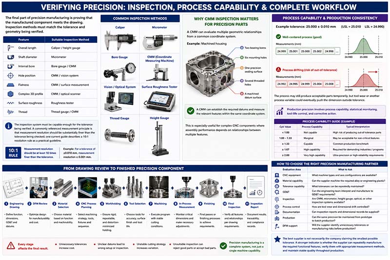
The final part of precision manufacturing is proving that the manufactured component meets the drawing.
Inspection methods must match the tolerance and geometry being verified.
Calipers are useful for general dimensional checks, while micrometers provide finer dimensional measurement. Bore gauges can be used for internal diameters, optical systems can inspect delicate or complex features, and Coordinate Measuring Machines (CMMs) can measure complex geometries and GD&T relationships.
For example:
| Feature | Suitable Inspection Method |
| Overall length | Caliper / height gauge |
| Shaft diameter | Micrometer |
| Internal bore | Bore gauge / CMM |
| Hole position | CMM / vision system |
| Flatness | CMM / surface measurement |
| Complex 3D profile | CMM / optical scanner |
| Surface roughness | Roughness tester |
| Thread | Thread gauge / CMM |
The inspection system must also be capable enough for the tolerance being verified. A commonly referenced measurement principle is that measurement resolution should be substantially finer than the tolerance being checked; one current precision-machining guide describes a 10:1 resolution rule as a practical guideline.
Why CMM inspection matters for precision parts
A CMM is valuable because it can evaluate multiple geometric relationships from a common coordinate system.
For example, imagine a machined housing containing:
- Two bearing bores
- Six mounting holes
- One precision sealing surface
- Several threaded holes
- A machined datum surface
Checking each dimension independently with hand tools may confirm individual sizes, but it may not fully verify whether the bores, holes, and surfaces maintain their required positional relationships.
A CMM can establish the required datums and measure the relevant features within the same coordinate system.
This is especially useful for complex CNC components where assembly performance depends on relationships between multiple features.
Process capability and production consistency
For production orders, checking one part is not enough.
Suppose a tolerance is:
25.000 ± 0.010 mm
and 100 parts are produced.
If the measurements are:
24.999, 25.001, 25.000, 25.002, 24.998…
the process is likely centered and tightly distributed.
But if measurements gradually move from:
24.992 → 24.995 → 24.999 → 25.004 → 25.008
the process may still produce acceptable parts temporarily, but tool wear or another process variable could eventually push the dimension outside tolerance.
This is why production precision involves process capability, statistical monitoring, tool-life control, and corrective action rather than simply measuring finished parts.
For higher-volume manufacturing, capability indicators such as Cpk can provide a useful way to evaluate how well a stable process operates within its specification limits. Values such as Cpk ≥ 1.33 are commonly used as a production benchmark, while more demanding industries or programs may require higher capability.
From drawing review to finished precision component
A reliable precision manufacturing workflow can be summarized as:
Engineering drawing → DFM review → Material selection → CNC process planning → Workholding → Tool selection → Machining → In-process measurement → Finishing → Final inspection → Inspection report
Each stage affects the final result.
If the drawing contains unnecessary tolerances, the manufacturer may face avoidable cost.
If the datum structure is unclear, the fixture and inspection strategy may not represent the actual assembly condition.
If the cutting strategy is unstable, dimensional variation can increase.
If the inspection equipment is unsuitable, a good part may be rejected or a bad part may be accepted.
Precision manufacturing is therefore a complete manufacturing system rather than a single machine capability.
How to Choose the Right Precision Manufacturing Partner
When sourcing precision CNC parts, customers should look beyond a manufacturer’s advertised machine accuracy.
A more useful evaluation should include:
| Evaluation Area | What to Ask |
| CNC equipment | What machine types and axis configurations are available? |
| Material capability | Can the supplier machine the required alloy or engineering plastic? |
| Tolerance capability | What tolerances can be repeatedly maintained? |
| GD&T | Can the engineering team interpret and manufacture to GD&T requirements? |
| Inspection | Are CMM, micrometer, height gauge, optical, or other inspection systems available? |
| Process control | How are tool wear and dimensional drift controlled? |
| Documentation | Can inspection reports and dimensional records be supplied? |
| Production | Can the same precision be maintained from prototype to batch production? |
| DFM support | Will the supplier identify unnecessary tolerances or manufacturing risks before production? |
The best supplier is not necessarily the company claiming the smallest possible tolerance. A stronger indicator is whether the supplier can repeatedly manufacture the required functional features, verify them with appropriate measurement methods, and maintain stable quality throughout production.
Precision Manufacturing with Xavier
For customers sourcing custom CNC machined components, Xavier approaches manufacturing precision from the complete process rather than focusing on a single machine specification.
From CNC milling and turning to complex precision components, the manufacturing strategy should begin with the engineering drawing and the actual function of the part. Critical bores, mating surfaces, hole locations, threads, profiles, and datum relationships can be evaluated before production so that the machining process and inspection method match the real requirements.
For example, a customer may require a general aluminum housing with several standard dimensions but only two critical bearing bores. Instead of unnecessarily applying ultra-tight tolerances across the entire component, the manufacturing process can concentrate precision control on those functional bores and their relationship with the relevant mounting surfaces.
This approach helps balance precision, repeatability, manufacturability, inspection requirements, lead time, and cost.
Whether you need a prototype, low-volume precision component, or repeat production of CNC machined metal parts, Xavier can work from your drawings, 3D models, tolerance requirements, and GD&T specifications to develop a practical manufacturing solution.
Ultimately, manufacturing precision is not about chasing the smallest number on a tolerance chart. It is about making the right feature accurate enough, often enough, and consistently enough to work reliably in the final assembly.
We are an integrated CNC machining manufacturer specializing in custom CNC machining and the production of precision metal components. Our capabilities cover a wide range of materials and applications, including robot parts, aerospace components, marine parts, automotive components, medical parts, and other precision-engineered products. We also provide CNC machining Nylon, CNC machining PEEK, and CNC machining Titanium, along with machining services for alloy steel, aluminum, brass, bronze, copper, Inconel alloys, Invar 36, low carbon steel, stainless steel, tool steel, ABS, FR4, G-10, PEI, PET, PMMA (acrylic), polycarbonate, polyethylene, polypropylene, POM (acetal), PPSU, PTFE, and PVC.
We are a CNC machining Nylon manufacturer, offering PEEK machining services in bulk, and you can contact us for Titanium machining prices. Feel free to contact us for your custom CNC machining requirements.
Some of the images and text in this article are collected and compiled from the internet. If there is anything inappropriate, please contact us for processing.