Precision CNC Drone Components: Materials, Tolerances, and Manufacturing Guide
Precision CNC drone components play an important role in UAV structural strength, assembly accuracy, weight control, and operational reliability. Common parts include motor mounts, gimbal brackets, arm connectors, electronic housings, landing gear components, and sensor mounting plates.
From a manufacturing and purchasing perspective, selecting a CNC supplier involves more than comparing prices. Material specifications, machining tolerances, surface treatments, production lead times, and inspection capabilities all influence the final component’s quality and cost.
Five Key Topics About Precision CNC Drone Components
- CNC-machined drone components and their functional requirements.
- Material selection for lightweight, high-strength UAV parts.
- CNC machining tolerances, GD&T, and surface finish.
- Manufacturing processes, production lead times, and cost optimization.
- Quality inspection and supplier selection.
1. CNC-Machined Drone Components and Their Functional Requirements
1.1 Common CNC Drone Parts
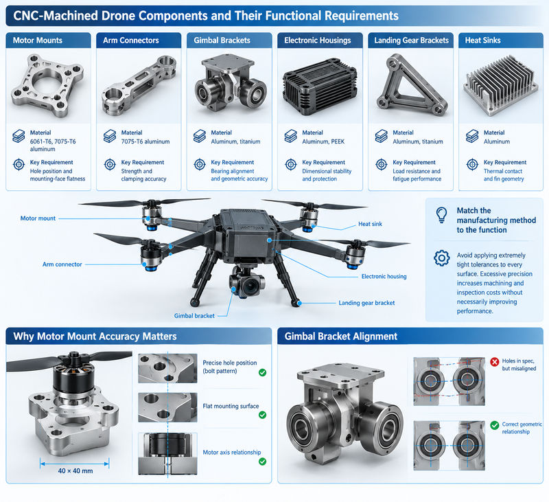
Different UAV components have different mechanical requirements. Motor mounts must withstand vibration and motor loads, while gimbal housings require accurate bearing alignment. Electronic enclosures prioritize dimensional stability, protection, and effective heat dissipation.
| Component | Common material | Critical requirement |
|---|---|---|
| Motor mounts | 6061-T6, 7075-T6 aluminum | Hole position and mounting-face flatness |
| Arm connectors | 7075-T6 aluminum | Strength and clamping accuracy |
| Gimbal brackets | Aluminum, titanium | Bearing alignment and geometric accuracy |
| Electronic housings | Aluminum, PEEK | Dimensional stability and protection |
| Landing gear brackets | Aluminum, titanium | Load resistance and fatigue performance |
| Heat sinks | Aluminum | Thermal contact and fin geometry |
The manufacturing method should match the component’s function. Applying extremely tight tolerances to every surface increases machining and inspection costs without necessarily improving performance.
1.2 Why Motor Mount Accuracy Matters
A motor mount transfers motor torque and thrust to the drone’s structure. Incorrect hole positions can complicate assembly, while a distorted mounting face can create uneven contact and additional stress during fastening.
For example, a motor mount with a 40 × 40 mm footprint may require a precisely controlled bolt pattern, a flat mounting surface, and a defined relationship between the motor axis and its mounting face.
The actual tolerances should be determined from the motor interface, fastening arrangement, structural analysis, and assembly requirements.
Gimbal brackets require similar attention. Two bearing bores can meet their individual diameter specifications but still be misaligned. Therefore, drawings should define important geometric relationships rather than specifying hole diameters alone.
2. Material Selection for Lightweight, High-Strength UAV Parts
Material selection influences component weight, strength, machinability, corrosion resistance, and total manufacturing cost. The best material depends on the load, operating environment, and intended service life.
2.1 Comparing Common CNC Materials
| Material | Approximate density | Main advantages |
|---|---|---|
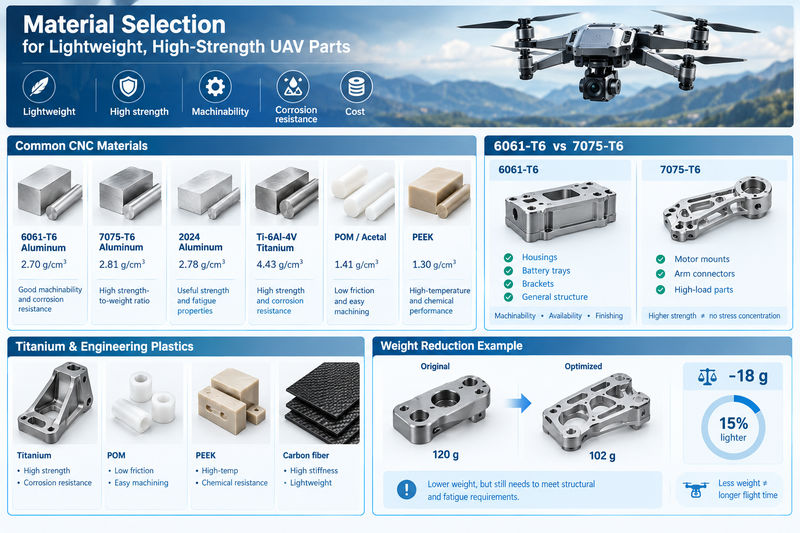
| 6061-T6 aluminum | 2.70 g/cm³ | Good machinability and corrosion resistance |
| 7075-T6 aluminum | 2.81 g/cm³ | High strength-to-weight ratio |
| 2024 aluminum | 2.78 g/cm³ | Useful strength and fatigue-related properties |
| Ti-6Al-4V titanium | 4.43 g/cm³ | High strength and corrosion resistance |
| POM/acetal | 1.41 g/cm³ | Low friction and easy machining |
| PEEK | 1.30 g/cm³ | High-temperature and chemical performance |
These densities are approximate reference values. Actual properties depend on material grade, temper, and manufacturing condition.
2.2 When to Choose 6061-T6 or 7075-T6 Aluminum
6061-T6 is suitable for many drone housings, battery trays, brackets, and general structural components. Its machinability, availability, and finishing options make it a practical choice for prototypes and production orders.
7075-T6 is often preferred for highly loaded components such as motor mounts and arm connectors. However, its higher strength does not eliminate stress concentrations caused by sharp corners, insufficient wall thickness, or poorly designed fastener holes.
7075 also requires appropriate corrosion protection in demanding environments. The specified alloy and temper should be confirmed before production; substituting 6061-T6 without engineering approval may change the component’s load capacity.
2.3 Titanium and Engineering Plastics
Titanium alloys are useful when high strength and corrosion resistance justify their higher material and machining costs. They are not automatically the lightest option, since titanium is considerably denser than aluminum.
POM is suitable for many spacers, bushings, and low-friction components. PEEK is appropriate for specialized applications requiring better temperature or chemical resistance.
Carbon fiber composites offer high stiffness-to-weight potential, but machining them requires suitable tooling, dust extraction, and measures to prevent fiber damage and delamination.
2.4 A Practical Weight-Reduction Example
Suppose an aluminum bracket originally weighs 120 g. After optimizing its pockets and ribs, the revised component weighs 102 g.
Weight reduction:
(120 − 102) ÷ 120 × 100 = 15%
The bracket saves 18 g, but the redesign must still satisfy structural and fatigue requirements. Reducing the mass of an individual component does not translate directly into the same percentage increase in flight endurance.
3. CNC Machining Tolerances, GD&T, and Surface Finish
Precision means controlling both individual dimensions and the relationships between features. A component may meet its dimensional limits but still fail to assemble because of misalignment or distortion.
3.1 Typical Tolerance Considerations
| Feature | Illustrative target | Key consideration |
|---|---|---|
| General external dimensions | ±0.05–0.10 mm | Size and assembly requirements |
| Mounting-hole position | ±0.02–0.05 mm | Mating-part alignment |
| Precision bearing bore | Defined by the required fit | Bearing type and operating conditions |
| Selected gimbal features | ±0.01–0.03 mm where justified | Axis and positional accuracy |
| General machined surfaces | Ra 1.6–3.2 µm | Surface function |
| Precision contact surfaces | Ra 0.4–0.8 µm where needed | Friction, contact, and wear |
These are preliminary engineering examples, not universal machining guarantees. Actual requirements must be defined on the component drawing.
3.2 Why GD&T Matters
Geometric Dimensioning and Tolerancing (GD&T) establishes how features relate to reference datums.
For a gimbal housing, the mounting base might serve as datum A, while another locating feature establishes datum B. Bearing-seat positions can then be controlled relative to these references.
This approach improves communication between design engineers, machinists, and inspectors. It also reduces the risk of producing individually accurate features that do not align during assembly.
3.3 Surface Finish and Anodizing
Surface roughness can affect friction, wear, sealing, and thermal contact. A smoother finish may be necessary for bearing seats or contact surfaces, but it is often unnecessary on noncritical external faces.
Aluminum anodizing adds another consideration: coating thickness can affect final dimensions. Precision bores, threaded holes, and mating faces may require masking or a defined machining allowance.
The drawing should state whether critical dimensions apply before or after surface treatment. This helps prevent parts from passing machining inspection but failing final assembly.
4. Manufacturing Processes, Lead Times, and Cost Optimization
4.1 Choosing the Right CNC Process
| Process | Typical application | Main benefit |
|---|---|---|
| 3-axis milling | Plates, trays, simple brackets | Economical machining |
| 4-axis machining | Components with features around a rotary axis | Fewer repositioning operations |
| 5-axis machining | Complex housings and angled features | Access to multiple faces |
| CNC turning | Shafts, bushings, rotary adapters | Efficient rotational machining |
| Precision grinding | Selected high-accuracy surfaces | Fine dimensional and finish control |
Five-axis machining is not always necessary. A simple mounting plate may be more economical on a three-axis machine, while a complex gimbal housing may benefit from fewer setups and improved positional consistency.
4.2 Controlling Thin-Wall Deformation
Lightweight drone components often contain deep pockets and thin walls. These features can vibrate during cutting or deform under clamping pressure.
A suitable process may involve rough machining, leaving finishing stock, controlling clamping forces, and completing critical surfaces with finishing passes. The component should then be inspected in an appropriate unclamped condition if the drawing defines its geometry in the free state.
For thin-walled parts, manufacturing strategy is essential to achieving repeatable dimensions.
4.3 Estimating Production Lead Time
| Manufacturing stage | Illustrative planning range |
|---|---|
| Drawing review and DFM | 1–3 working days |
| Material procurement | 2–7 working days |
| Programming and setup | 1–4 working days |
| Prototype machining | 1–5 working days |
| Surface finishing | 2–7 working days |
| Final inspection | 1–3 working days |
These are planning estimates rather than guaranteed delivery times. Some operations can overlap, while complex geometries, special materials, outsourced coatings, and first-article inspection may extend the schedule.
When requesting quotations, ask suppliers to distinguish prototype lead time from repeat-production lead time.
4.4 Understanding CNC Machining Costs
CNC component costs typically include raw material, programming, setup, machine time, tooling, surface treatment, inspection, and scrap risk.
Consider an illustrative order of 10 aluminum brackets:
- Programming and setup: $200
- Machining: $35 per part
- Finishing and inspection: $10 per part
Total cost = $200 + 10 × ($35 + $10) = $650.
The resulting unit cost is $65. For 100 parts, assuming the same setup cost and unchanged per-part costs, the total becomes $4,700, or $47 per part.
These figures are hypothetical and demonstrate how setup costs affect unit pricing.
To reduce costs, engineers can use standard tool sizes, avoid unnecessarily deep narrow pockets, specify realistic tolerances, and simplify machining setups without compromising critical functions.
5. Quality Inspection and Supplier Selection
A reliable CNC supplier should demonstrate that the finished components meet the drawing requirements through suitable inspection and documentation.
5.1 Inspection Methods
| Inspection equipment | Typical purpose |
|---|---|
| Digital caliper | General dimensions |
| Micrometer | Precision thicknesses and diameters |
| Bore gauge or pin gauge | Hole and bore measurements |
| Height gauge and surface plate | Datum-based measurements |
| Coordinate measuring machine (CMM) | Complex dimensions and geometric relationships |
| Surface roughness tester | Ra measurements |
Inspection methods should be selected according to the component’s critical features. A complex gimbal bracket may require CMM inspection, while a simple noncritical spacer may need only basic dimensional checks.
5.2 First-Article Inspection and Traceability
For a new part, first-article inspection helps establish whether the manufacturing process meets the drawing before repeat production begins.
Depending on project requirements, documentation may include:
- Material grade and temper verification.
- Measurements of critical dimensions and GD&T features.
- Surface-finish and coating verification.
- Drawing revision and inspection records.
- Material certificates and batch traceability.
- Records of approved deviations.
For a production batch, inspection frequency should reflect process stability, component risk, quantity, and customer requirements.
5.3 Evaluating a CNC Supplier
Before placing an order, confirm that the supplier can:
- Review CAD models and technical drawings.
- Manufacture the specified material and geometry.
- Control critical dimensions and surface treatments.
- Provide agreed inspection reports and material documentation.
- Explain prototype and repeat-production lead times.
- Identify manufacturing risks before production begins.
For regulated or safety-critical aviation applications, additional qualification, traceability, and applicable aerospace requirements may be necessary.
Custom Precision CNC Drone Components from Xavier
Xavier provides CNC machining services for international customers requiring custom metal and engineering-plastic components. UAV-related projects may include aluminum brackets, motor mounts, housings, structural connectors, and precision mounting components manufactured to customer drawings.
Depending on the design, manufacturing requirements may involve CNC milling, turning, precision boring, grinding, and secondary surface finishing.
To request a quotation, prepare a 3D CAD file, technical drawing, material specification, required tolerances, surface-finish requirements, and order quantity. Providing these details allows the manufacturing team to evaluate machinability, production costs, and delivery requirements more effectively.
If you are developing a new drone platform or sourcing custom UAV parts, contact Xavier to discuss material selection, manufacturing feasibility, dimensional control, and production planning.
As an integrated CNC machining manufacturer and trading company, we specialize in CNC machining services and contract manufacturing for a wide range of metal components. Our capabilities cover CNC machining aluminum, CNC machining stainless steel, and CNC machining PEEK. We work with a broad selection of metals, including alloy steel, brass, bronze, copper, Inconel, Invar 36, mild steel, titanium, and tool steel, as well as engineering plastics such as ABS, FR4, G-10, nylon, PEI, PET, PMMA, polycarbonate, polyethylene, polypropylene, POM, PPSU, PTFE, and PVC. Our custom-machined components serve diverse industries, including robotics, aerospace, marine, automotive, medical equipment, and precision engineering.
As a CNC aluminum machining manufacturer, we provide bulk stainless steel machining services and welcome inquiries about PEEK CNC machining prices. Contact us to discuss your project requirements and receive a tailored manufacturing solution.
Some of the images and text in this article are collected and compiled from the internet. If there is anything inappropriate, please contact us for processing.