Strain vs Stress: What’s the Difference and Why It Matters in Engineering and CNC Machining
Material failure is one of the biggest concerns in engineering, manufacturing, and product design. Whether you’re machining aerospace titanium, automotive steel, or aluminum precision components, understanding the relationship between stress and strain is essential for selecting materials, optimizing designs, and preventing unexpected failures.
Although these two terms are often mentioned together, they describe completely different mechanical behaviors. Stress measures the internal force acting on a material, while strain measures the material’s resulting deformation. Engineers rely on both values to determine whether a component will remain elastic, permanently deform, or ultimately fracture.
In CNC machining, knowing how stress and strain interact allows manufacturers to choose suitable materials, improve machining strategies, reduce residual stress, and produce parts capable of withstanding real-world working conditions.
Six Google Top-Ranking Topics Related to Strain vs Stress
1. What Are Stress and Strain? Understanding the Fundamental Difference
2. Types of Stress and Types of Strain in Engineering Materials
3. Stress vs Strain Comparison Table: Key Differences
4. The Stress-Strain Curve Explained
5. Why Stress and Strain Matter in CNC Machining and Product Design
6. Common Engineering Applications and Practical Examples
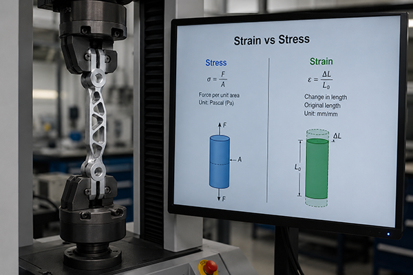
What Are Stress and Strain? Understanding the Fundamental Difference
Although stress and strain are closely related, they describe different physical quantities.
Stress refers to the internal resisting force generated inside a material when an external load is applied.
Mathematically,
Stress (σ) = Force / Area
Its SI unit is Pascal (Pa), although engineers commonly use MPa or GPa because engineering materials usually experience much larger loads.
For example:
- A steel rod subjected to 20,000 N over an area of 100 mm² experiences approximately 200 MPa of stress.
- If the same force is applied to a rod with half the cross-sectional area, the stress doubles.
This illustrates why thin sections of components generally fail before thicker ones under identical loading conditions.
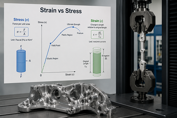
In contrast, strain describes how much a material deforms relative to its original size.
The formula is:
Strain (ε) = Change in Length / Original Length
Unlike stress, strain has no unit because it is simply a ratio.
For example:
| Original Length | Elongation | Strain |
|---|---|---|
| 100 mm | 0.2 mm | 0.002 |
| 200 mm | 0.4 mm | 0.002 |
Although the specimens have different dimensions, both experience exactly the same strain because the percentage deformation is identical.
This distinction is extremely important in engineering because two components may experience identical strain while carrying very different stress levels depending on the material.
Stress Represents the Cause, While Strain Represents the Effect
A useful way to understand the relationship is:
| Concept | Stress | Strain |
|---|---|---|
| Meaning | Applied internal force | Resulting deformation |
| Represents | Cause | Effect |
| Unit | MPa, GPa | Dimensionless |
| Depends On | Applied load and area | Material behavior |
| Measured By | Load cells, pressure calculations | Extensometers, strain gauges |
Simply put:
Stress tells engineers how hard a material is being pushed or pulled.
Strain tells engineers how much the material actually stretches or compresses.
A high-strength alloy and a soft plastic may experience identical strain values while carrying completely different stress loads.
Why Engineers Must Measure Both
Considering only stress can lead to incorrect design decisions.
Imagine two shafts carrying the same torque:
- Shaft A is made from hardened alloy steel.
- Shaft B is made from nylon.
Although the applied stress may be similar, the nylon shaft will deform significantly more because its elastic modulus is much lower.
Conversely, considering only strain also provides incomplete information.
A titanium aerospace bracket and an aluminum bracket may deform by the same percentage, yet the titanium component can safely sustain much higher stress before yielding.
For this reason, engineers always evaluate stress, strain, and material properties together, rather than relying on a single value.
Real CNC Manufacturing Example
Consider a CNC-machined aluminum mounting bracket installed inside an industrial robot.
During operation, the bracket supports a cyclic load of approximately 8 kN.
Finite Element Analysis predicts:
| Parameter | Value |
|---|---|
| Maximum Stress | 165 MPa |
| Maximum Strain | 0.0024 |
| Yield Strength of Aluminum 7075-T6 | 503 MPa |
| Safety Factor | ≈3.0 |
Although the stress is well below the yield strength, the corresponding strain indicates only slight elastic deformation.
Once the load is removed, the bracket returns to its original shape without permanent damage.
If the same bracket were manufactured from ABS plastic instead of aluminum, the strain would be several times higher, resulting in excessive deflection and poor dimensional accuracy despite carrying a similar external load.
This example demonstrates why material selection depends on both stress and strain—not just one parameter.
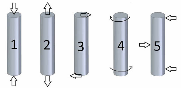
Types of Stress and Types of Strain in Engineering Materials
In real engineering applications, loads rarely act in only one direction. Components used in aircraft, automotive systems, industrial machinery, and CNC-machined assemblies are often subjected to multiple loading conditions simultaneously. As a result, engineers classify stress and strain into several categories based on how forces are applied and how materials respond.
Understanding these different types is essential for selecting the right material, predicting failure modes, and designing durable mechanical components.
1. Tensile Stress and Tensile Strain
Tensile stress occurs when forces pull a material apart along its length. The material experiences elongation, producing tensile strain.
This is one of the most common loading conditions in structural engineering.
Typical applications include:
- Suspension cables
- Bolts under preload
- Tie rods
- Aircraft structural members
- Fasteners in machinery
For example, a stainless steel bolt securing two machine components experiences tensile stress when tightened. If the applied load remains below the yield strength, the bolt stretches elastically and returns to its original length after the load is removed. However, excessive tensile stress can cause permanent elongation or fracture.
2. Compressive Stress and Compressive Strain
Compressive stress develops when forces push inward on a material, causing it to shorten.
Examples include:
- Machine columns
- Hydraulic press components
- Building support pillars
- CNC machine frames
While many metals can withstand high compressive loads, slender components are susceptible to buckling long before the material itself fails. Therefore, engineers must evaluate both material strength and geometric stability during design.
3. Shear Stress and Shear Strain
Shear stress acts parallel to a surface rather than perpendicular to it. It causes adjacent layers within a material to slide relative to one another.
Shear loading is particularly important in manufacturing because many machining operations involve shear deformation.
Examples:
- Milling cutters removing chips
- Drilling operations
- Riveted joints
- Keys and splines transmitting torque
- Punching and blanking processes
In CNC machining, chip formation is primarily the result of localized shear stress exceeding the material’s shear strength. Tool geometry, cutting speed, and feed rate all influence the magnitude of shear stress generated during machining.
Stress vs Strain Comparison Table: Key Differences in Engineering Applications
In engineering design and CNC machining, stress and strain are often analyzed together, but they represent fundamentally different behaviors. A structured comparison helps clarify how each parameter affects material performance under load.
Below is a practical engineering-oriented comparison used in material selection and simulation workflows.
Engineering Comparison Table
| Category | Stress (σ) | Strain (ε) |
|---|---|---|
| Definition | Internal resisting force per unit area | Relative deformation of material |
| Formula | σ = F / A | ε = ΔL / L₀ |
| Unit | Pa / MPa / GPa | Dimensionless |
| Physical Meaning | Load intensity inside material | Shape change response |
| Depends on | External force + cross-section | Material elasticity |
| Measured by | Load cells, simulation (FEA) | Strain gauges, extensometers |
| Failure indicator | Yield strength / ultimate strength | Maximum elongation limit |
| Engineering role | Design load capacity | Deformation control |
CNC Engineering Insight: Why This Table Matters
In CNC machining environments, this distinction directly affects part performance:
- A high-stress region in a machined aluminum bracket may still be safe if strain remains within elastic limits.
- A low-stress polymer component may still fail due to excessive strain (deformation), even without reaching material strength limits.
For example:
- Aluminum 6061-T6:
- High stress tolerance (~275 MPa yield)
- Low strain under load (stiff behavior)
- Nylon 6:
- Lower stress capacity (~70 MPa)
- High strain capability (flexible deformation)
This means design failure is not always caused by stress exceeding limits—it can also be caused by uncontrolled strain.
The Stress-Strain Curve Explained: Elasticity, Yielding, and Fracture Behavior
The stress-strain curve is one of the most important graphical tools in mechanical engineering. It shows how a material responds when load is gradually applied until failure.
This curve is widely used in material testing labs, finite element analysis (FEA), and CNC part validation.
1. Elastic Region (Hooke’s Law Zone)
In the initial linear region, stress is proportional to strain:
σ ∝ ε
This is known as the elastic region.
y=xy = xy=x
Although simplified, this linear relationship represents Hooke’s Law behavior.
Key characteristics:
- Material returns to original shape after unloading
- No permanent deformation
- Linear stress-strain relationship
- Slope = Young’s Modulus (stiffness indicator)
Example:
- Steel has a steep slope → very stiff
- Rubber has a shallow slope → highly flexible
2. Yield Point (Permanent Deformation Begins)
The yield point marks the transition from elastic to plastic deformation.
Once stress exceeds this point:
- Material no longer fully recovers
- Permanent deformation begins
Typical yield strength values:
| Material | Yield Strength |
|---|---|
| Mild Steel | ~250 MPa |
| Aluminum 6061 | ~275 MPa |
| Titanium Grade 5 | ~830 MPa |
In CNC machining design, engineers always ensure working stress remains below yield strength to avoid permanent deformation of precision components.
3. Plastic Region (Permanent Deformation Zone)
Beyond the yield point, the material enters the plastic region.
Characteristics:
- Non-linear curve behavior
- Internal atomic structure begins to slip
- Permanent shape change occurs
This region is critical in:
- Metal forming
- Deep drawing
- Forging processes
In CNC parts, plastic deformation is usually considered failure unless intentional (e.g., spring forming).
4. Ultimate Tensile Strength (UTS)
UTS is the maximum stress a material can withstand before necking begins.
After this point:
- Cross-sectional area reduces locally
- Stress concentration increases rapidly
- Failure becomes imminent
Typical UTS values:
| Material | UTS |
|---|---|
| Aluminum 7075-T6 | ~570 MPa |
| Stainless Steel 304 | ~505 MPa |
| Titanium Grade 5 | ~900 MPa |
For CNC structural components, UTS provides a safety ceiling in high-load applications.
5. Fracture Point (Final Failure)
The final stage of the curve is fracture.
At this point:
- Atomic bonds completely break
- Material separates into two or more pieces
- No further load can be supported
Different materials behave differently:
- Ductile materials (steel) show significant deformation before fracture
- Brittle materials (ceramics) fail suddenly with minimal strain
Why Stress and Strain Matter in CNC Machining and Product Design
In CNC manufacturing, stress and strain are not theoretical concepts—they directly influence part durability, dimensional accuracy, and long-term reliability.
1. Residual Stress from Machining Operations
During CNC milling, drilling, and turning:
- Cutting forces generate localized heat
- Uneven cooling introduces internal stress
- Material surface layers may deform plastically
This leads to residual stress, which can cause:
- Warping after machining
- Dimensional instability
- Reduced fatigue life
For precision aerospace components, stress-relief heat treatment is often required after machining.
2. Tool Force vs Material Response
Different materials respond differently to machining forces:
| Material | Cutting Stress | Deformation (Strain) |
|---|---|---|
| Aluminum | Low | Low |
| Stainless Steel | High | Medium |
| Titanium | Very High | Low but concentrated |
| PEEK Polymer | Low | High |
Titanium alloys, for example, generate high cutting stress but resist plastic deformation, making them difficult to machine but dimensionally stable after processing.
3. Dimensional Accuracy and Elastic Recovery
After machining, parts may slightly “spring back” due to elastic strain recovery.
Example:
- Thin-walled aluminum housing may deform during clamping
- After release, it partially returns, causing dimensional deviation
This is why CNC engineers use:
- Soft jaws
- Vacuum fixtures
- Multi-step rough + finish machining
4. Fatigue Life in Repeated Loading
Components under cyclic stress experience gradual strain accumulation.
Typical failures include:
- Gear shafts
- Automotive suspension parts
- Robot arm joints
Even if stress is below yield strength, repeated strain cycles can cause fatigue failure over time.
Xavier Engineering Recommendation
In real CNC engineering applications, stress tells you whether a material can survive a load, while strain tells you whether it can maintain its shape. High-performance components must satisfy both conditions simultaneously.
At Xavier Precision Manufacturing, CNC parts are engineered with strict stress-strain analysis before production. From aerospace titanium brackets to industrial automation components, every design is optimized for:
- Controlled stress distribution
- Minimal elastic deformation
- Long fatigue life stability
This ensures each machined part performs reliably under real working conditions—not just in theory, but in actual industrial environments.
We are a vertically integrated CNC machining manufacturer and trading company, specializing in CNC contract manufacturing and the production of a wide range of precision metal parts. Our capabilities cover multiple materials and customized machining solutions for global customers. We also provide professional surface finishing options, including
cnc anodizing surface finishing,
cnc electroless nickel surface finishing, and
cnc electrogalvanizing surface finishing, ensuring enhanced durability, corrosion resistance, and product performance.
In addition, we are a cnc anodizing surface finishing manufacturer, providing large-scale cnc electroless nickel surface finishing service, and offering competitive cnc electrogalvanizing surface finishing price. Please feel free to contact us for more details or customized solutions.
Some of the images and text in this article are collected and compiled from the internet. If there is anything inappropriate, please contact us for processing.