
Difference in MIG and TIG: A Detailed Comparison for Metal Part Manufacturing
MIG and TIG welding are two of the most widely used arc welding processes in metal fabrication, but they are not interchangeable in every application. Both can produce strong permanent joints, yet the way they generate the arc, introduce filler metal, control heat, and form the weld bead is fundamentally different.
For customers ordering custom metal parts, welded assemblies, brackets, frames, housings, tubes, or CNC-machined components, the difference between MIG and TIG is more than simply choosing between two welding machines. The welding method can influence production speed, appearance, dimensional accuracy, distortion, material compatibility, post-processing requirements, and ultimately the cost of the finished component.
The following comparison focuses on the practical differences that matter when specifying or manufacturing metal components.
1. MIG and TIG Welding Principles: How the Two Processes Actually Work
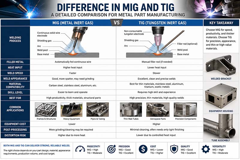
Although both MIG and TIG use an electric arc to melt metal and form a joint, their electrode and filler-metal systems are fundamentally different.
MIG stands for Metal Inert Gas welding and is commonly classified technically as Gas Metal Arc Welding (GMAW). A continuously fed wire electrode passes through the welding gun and acts as both the electrode and, in most applications, the filler metal. As the wire contacts the welding zone, the electric arc melts the wire and base material simultaneously. Shielding gas flows around the arc to reduce atmospheric contamination.
TIG stands for Tungsten Inert Gas welding and is technically known as Gas Tungsten Arc Welding (GTAW). TIG uses a non-consumable tungsten electrode to create the arc. The filler metal, when required, is normally supplied separately by the operator using a filler rod. This gives the welder independent control over arc heat and filler addition.
| Feature | MIG Welding | TIG Welding |
|---|---|---|
| Technical name | GMAW | GTAW |
| Electrode | Consumable wire | Non-consumable tungsten |
| Filler metal | Continuously fed automatically | Added separately by hand when required |
| Shielding gas | Argon, CO₂, or gas mixtures depending on material | Usually argon; helium mixtures may also be used |
| Operator control | Relatively simple | Highly controlled and technique-dependent |
| Welding speed | Generally faster | Generally slower |
| Heat control | Good | Excellent |
| Weld appearance | Good, but may require finishing | Typically very clean |
| Typical use | Production and structural fabrication | Precision and appearance-critical welding |
The practical difference becomes obvious during welding. With MIG, the operator controls the gun position and travel speed while the machine continuously supplies wire. This makes it suitable for relatively long welds and repetitive production.
With TIG, the operator controls the torch with one hand and may feed filler metal with the other. On many TIG systems, amperage can also be adjusted during welding. This creates a much higher degree of control over the weld pool.
For example, imagine a 500 mm-long weld on a 5 mm carbon-steel bracket. If the primary objective is production efficiency, MIG may be the more practical solution because the continuously fed wire allows the operator to deposit filler metal rapidly. If the same bracket were made from thin stainless steel and the weld were located on a highly visible surface, TIG could be preferable because the operator can control the heat and filler addition much more precisely.
2. Welding Speed, Productivity, and Deposition Rate
The difference in welding speed is one of the clearest distinctions between MIG and TIG.
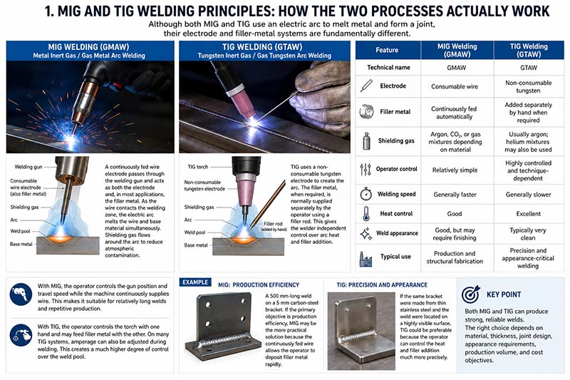
MIG is generally selected when production volume is important. Because the filler wire is continuously supplied, the operator does not have to repeatedly stop the arc to add filler material. This supports longer continuous welds and higher deposition rates.
TIG takes considerably more manual coordination. The operator must maintain the tungsten electrode at the correct distance, control the arc, move the torch, and feed filler rod when necessary. This makes TIG slower, especially when producing long weld seams.
Some manufacturing references report typical deposition rates around 4–8 kg/h for MIG and approximately 1–2 kg/h for TIG under suitable production conditions, although actual values vary significantly with welding current, wire diameter, transfer mode, joint design, material, operator technique, and equipment.
The numbers should therefore be viewed as representative ranges rather than universal production specifications.
| Production factor | MIG | TIG |
|---|---|---|
| Filler delivery | Continuous | Manual/intermittent |
| Typical productivity | High | Lower |
| Long weld seams | Excellent | Less efficient |
| Repetitive production | Excellent | More labor-intensive |
| Fine weld control | Moderate | Excellent |
| Operator coordination | Lower | Higher |
Consider a manufacturer producing 1,000 identical steel brackets. Each bracket requires approximately 400 mm of welding.
If the weld design is suitable for MIG, the continuous wire feed can significantly reduce the time spent on each bracket. The productivity advantage becomes increasingly important as production quantities increase.
TIG can still be technically appropriate, but using TIG simply because it can produce a beautiful weld may not be economically sensible for a high-volume component if MIG can already meet the required strength, dimensional, and appearance specifications.
This is an important point for purchasing engineers: the slower process is not automatically the better process. Welding should be selected according to the actual engineering requirement rather than perceived quality alone.
3. Material Compatibility and Recommended Material Thickness
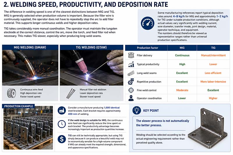
Both MIG and TIG can be used on common engineering metals, including carbon steel, stainless steel, and aluminum. TIG also provides particularly strong advantages when working with thin sections, reactive metals, and applications where precise heat input is important.
Carbon Steel
MIG is commonly used for carbon-steel structures, brackets, frames, supports, machinery components, and fabricated assemblies.
For example, a 6 mm carbon-steel mounting bracket with multiple fillet welds is generally a good candidate for MIG because the process can provide high productivity without requiring the level of manual control associated with TIG.
TIG can also weld carbon steel effectively, especially when the component requires a particularly clean appearance, precise penetration, or controlled heat input.
Stainless Steel
Both processes are widely applicable to stainless steel, but TIG is often preferred when surface appearance and heat control are critical.
Stainless steel can discolor when excessive heat is introduced. On visible components such as equipment panels, decorative structures, food-processing components, and precision enclosures, controlling the heat-affected area can reduce unwanted discoloration and distortion.
TIG allows the operator to carefully control the weld pool, making it suitable for thin stainless-steel sections and appearance-sensitive welds.
Aluminum
Aluminum is another material where both MIG and TIG are widely used.
MIG can be highly productive for thicker aluminum components and larger production quantities. TIG is often preferred when welding thin aluminum or when the weld must have a very controlled and clean appearance. TIG also allows the operator to carefully manage the molten pool, which is useful because aluminum conducts heat rapidly and can become difficult to control as the workpiece temperature changes.
| Material | MIG Suitability | TIG Suitability | Typical Reason |
|---|---|---|---|
| Carbon steel | Excellent | Excellent | MIG for productivity, TIG for precision |
| Stainless steel | Excellent | Excellent | TIG favored for appearance and heat control |
| Aluminum | Excellent | Excellent | MIG for production, TIG for precision |
| Titanium | Limited/specialized | Excellent | TIG provides precise control and shielding |
| Copper | Possible with suitable setup | Excellent/specialized | TIG offers controlled heat input |
| Nickel alloys | Possible | Excellent | TIG useful for precision applications |
Material thickness is equally important.
A simplified comparison often places MIG in a stronger position as thickness increases, while TIG is particularly useful for thin-gauge components. Some manufacturing references describe TIG as particularly suitable for approximately 0.5–3 mm sections, while MIG becomes increasingly attractive for thicker material, although actual capability depends heavily on machine settings, joint design, transfer mode, and operator skill.
This should not be interpreted as a strict thickness boundary. A skilled welder can use TIG on thicker materials, and MIG can be used on relatively thin sheet metal with appropriate settings.
The important question is not simply:
“How thick is the material?”
It is:
“How much heat control does this particular joint require?”
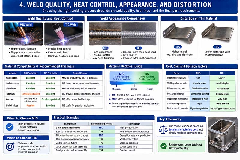
4. Weld Quality, Heat Control, Appearance, and Distortion
Many customers assume that TIG automatically produces a stronger weld than MIG. This is an oversimplification.
Both MIG and TIG can produce strong, durable welds when the correct filler metal, joint preparation, welding parameters, shielding, and operator technique are used. Weld strength depends on the complete welding procedure rather than the process name alone.
The major advantage of TIG is precise control.
Because the tungsten electrode does not continuously melt into the weld pool, the operator can control the arc independently from filler-metal addition. This makes it easier to manipulate the size of the molten pool and limit unnecessary heat input.
For thin stainless steel, for example, excessive heat can produce:
- Warping
- Burn-through
- Excessive discoloration
- Changes in the heat-affected zone
- Dimensional deviation
- Difficult post-weld finishing
TIG can reduce these problems when performed correctly because the operator can carefully regulate the arc.
MIG, however, is not inherently a low-quality welding method. Modern MIG equipment can produce very consistent welds, especially in controlled production environments. The process can also be easier to automate because wire feeding is continuous.
Weld Appearance
TIG usually produces the cleaner visual appearance.
A properly executed TIG weld can have a narrow, consistent bead with controlled ripples and relatively little spatter. This is why TIG is commonly selected for visible stainless-steel components, tubing, precision assemblies, and products where the weld itself is part of the appearance.
MIG can also produce excellent-looking welds, but depending on the process settings and shielding gas, spatter or a more pronounced bead profile may occur. Additional grinding, sanding, or polishing may therefore be required when a cosmetic finish is specified.
For CNC-machined or precision-fabricated components, this distinction matters because welding may be followed by machining.
For example, a fabricated aluminum housing may first be welded and then CNC machined on critical mounting surfaces. Excessive weld distortion can create additional machining requirements. If a flange needs to remain within a tight dimensional tolerance after welding, the manufacturing sequence may need to include controlled welding, stress management, fixture support, and subsequent CNC machining.
This is where welding and CNC machining should be considered as one manufacturing process rather than two unrelated operations.
5. Cost, Skill Requirements, and How to Choose MIG or TIG for Custom Parts
MIG is generally easier to learn and faster for production welding, while TIG requires greater operator coordination and experience. This difference directly affects manufacturing cost.
MIG’s continuous wire feed simplifies the welding movement. The operator generally needs to maintain the correct torch angle, travel speed, stick-out, and distance while the machine supplies filler metal automatically.
TIG requires substantially more coordination.
The operator may simultaneously control:
- Torch position
- Tungsten-to-workpiece distance
- Travel speed
- Filler-rod addition
- Welding current
- Shielding-gas coverage
This explains why TIG welding often carries a higher labor cost per unit of weld length.
However, choosing MIG simply because it is cheaper can also be a mistake.
Suppose a customer needs 300 stainless-steel sensor housings made from 1.0 mm sheet metal. The weld is visible and the enclosure must remain dimensionally stable.
A low-cost MIG process might initially appear attractive. But if it creates excessive spatter, distortion, or discoloration, the manufacturer may need additional grinding, straightening, cleaning, polishing, and inspection.
The apparent welding saving can therefore disappear in secondary operations.
TIG may have a higher welding labor cost but lower finishing requirements.
A simplified manufacturing-cost comparison might look like this:
| Cost factor | MIG | TIG |
|---|---|---|
| Machine productivity | High | Lower |
| Welding labor per meter | Usually lower | Usually higher |
| Filler consumption | Continuous wire | Manual filler |
| Post-weld cleanup | Sometimes required | Usually lower |
| Precision on thin material | Moderate to high | Very high |
| Automation potential | High | More difficult |
| Best economic scenario | High-volume production | Precision/appearance-critical parts |
The correct choice is therefore based on total manufacturing cost, not simply machine operating cost.
6. Practical Examples: When MIG Makes More Sense and When TIG Is Better
Consider a CNC machining customer ordering a steel machine frame.
The frame consists of 8 mm carbon-steel plates, several 500 mm-long fillet welds, and a production quantity of 200 units.
In this situation, MIG would normally be an attractive option. The material is relatively thick, the welds are long, and production quantity is high. High deposition efficiency and continuous wire feeding can help reduce cycle time.
Now consider a different component: a 1.2 mm stainless-steel enclosure with short visible welds around the edges.
Here, TIG may be the better choice. The weld length is relatively short, appearance is important, and the thin material increases the risk of distortion and burn-through.
A third example is an aluminum manifold with machined sealing surfaces.
The welding process must be selected carefully because heat can distort the component before final CNC machining. TIG may be advantageous for controlling the weld zone on smaller precision assemblies, while MIG can be highly effective when production volume and thicker aluminum sections dominate the requirements.
| Example Part | Recommended Process | Main Reason |
|---|---|---|
| 8 mm carbon-steel frame | MIG | High productivity |
| 1.0–1.5 mm stainless enclosure | TIG | Heat control and appearance |
| Thick aluminum structural bracket | MIG | Deposition rate and production |
| Thin aluminum precision component | TIG | Weld-pool control |
| Visible stainless tubing | TIG | Clean appearance |
| Large production steel assembly | MIG | Lower cycle time |
| Small precision welded assembly | TIG | Greater control |
7. MIG vs TIG: A Practical Decision Guide
For engineers and purchasing teams, the easiest way to select between MIG and TIG is to evaluate the part from several directions instead of focusing on only one parameter.
Choose MIG when:
- Production speed is a major concern.
- The component contains long weld seams.
- The material is medium or relatively thick.
- Production volume is high.
- The weld will not be highly visible.
- Minor post-weld finishing is acceptable.
- Automation or robotic welding may be considered.
Choose TIG when:
- The material is thin.
- Weld appearance is important.
- Heat input must be carefully controlled.
- The component has tight dimensional requirements.
- The weld is located in a visible area.
- The material is stainless steel, aluminum, titanium, or another alloy requiring careful heat management.
- The quantity is lower but weld quality and precision are more important.
There is also no requirement to use only one process throughout an entire project.
A fabricated assembly may use MIG for structural joints and TIG for visible or precision-critical sections. The final process selection can therefore be based on the function of each individual joint.
8. What Customers Should Specify When Ordering Welded CNC Parts
When requesting a quotation for custom welded parts, simply writing “MIG welding” or “TIG welding” is often not enough.
A useful drawing or RFQ should ideally identify:
- Base material and grade
- Material thickness
- Weld location
- Weld size
- Fillet or butt-weld geometry
- Weld length
- Appearance requirements
- Dimensional tolerances
- Required post-weld machining
- Surface-finish requirements
- Inspection requirements
- Whether grinding or polishing is allowed
For example, instead of specifying:
“Weld stainless-steel bracket.”
A more useful specification would be:
“304 stainless steel, 2.0 mm sheet, TIG weld, continuous fillet weld, visible exterior surface, minimize discoloration and distortion, grind/polish weld area to specified finish.”
This gives the manufacturer enough information to evaluate the process properly.
For a production steel frame, the specification might instead favor MIG because production efficiency is more important:
“ASTM/AISI-compatible carbon steel, 6 mm plate, MIG welding, continuous fillet welds, structural application, dimensional inspection after welding.”
The more accurately the welding requirements are defined, the easier it becomes for the manufacturer to select the appropriate process, fixture design, welding parameters, and post-processing sequence.
9. Final Comparison: MIG or TIG?
There is no universal winner in the difference between MIG and TIG welding.
MIG is primarily a productivity-oriented process. Its continuously fed consumable wire makes it particularly suitable for repetitive welding, longer seams, thicker materials, and high-volume manufacturing.
TIG is primarily a control-oriented process. Its non-consumable tungsten electrode and separate filler-metal system allow the welder to carefully manage heat, penetration, filler addition, and weld appearance.
In simple terms:
MIG = speed, productivity, and efficient production.
TIG = precision, heat control, and high-quality appearance.
For custom metal components, the best process is the one that meets the mechanical, dimensional, cosmetic, and production requirements at the lowest overall manufacturing cost.
At Xavier, we approach welded CNC components from the complete manufacturing perspective rather than selecting a welding process in isolation. CNC machining, welding, material selection, surface finishing, dimensional inspection, and post-weld machining can all affect the final performance of a part. By evaluating the material, thickness, joint geometry, production quantity, tolerances, and appearance requirements together, Xavier can recommend a practical MIG or TIG welding solution for each custom component.
Whether you need high-volume MIG-welded assemblies, precision TIG-welded stainless-steel parts, aluminum components, or welded parts that require subsequent CNC machining, the objective is the same: achieve the required quality without adding unnecessary manufacturing cost or processing steps.
We are an integrated CNC machining manufacturer specializing in custom CNC machining and the production of precision metal parts. We also provide professional CNC anodizing surface finishing, CNC electrogalvanizing surface finishing, and CNC passivation surface finishing to meet different part performance and appearance requirements.
We are a professional CNC anodizing surface finishing manufacturer, offering CNC electrogalvanizing surface finishing services for bulk production and helping customers check CNC passivation surface finishing prices. Feel free to contact us for more information.
Some of the images and text in this article are collected and compiled from the internet. If there is anything inappropriate, please contact us for processing.