
Core Knowledge Points & Themes for CNC Milling Manufacturing
- What CNC Milling Manufacturing Means in Modern Industry
- CNC Milling Machines and Axis Capabilities
- Materials Commonly Used in CNC Milling Manufacturing
- Accuracy, Tolerances, and Dimensional Control
- Surface Finish and Functional Performance
- Tooling Strategy and Cutting Parameter Optimization
- Design for CNC Milling Manufacturing (DFM)
- Production Scale: Prototype to Mass Manufacturing
- Quality Control and Inspection Systems
- How to Choose a CNC Milling Manufacturing Partner
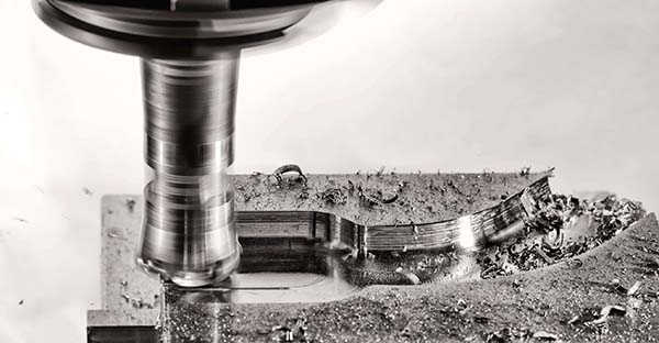
What CNC Milling Manufacturing Means in Modern Industry
CNC milling manufacturing is a subtractive manufacturing process where material is precisely removed from a workpiece using computer-controlled rotating cutting tools. Unlike manual machining, CNC milling manufacturing relies on digital programming, repeatable toolpaths, and automated control, enabling consistent production of complex components.
CNC milling manufacturing is widely used to produce:
- Structural components with tight geometric relationships
- Precision housings, frames, and brackets
- Functional parts with slots, pockets, and complex surfaces
- Critical components requiring repeatability across batches
In modern manufacturing, CNC milling is often the core process that connects product design with scalable production, especially in industries that demand accuracy, strength, and reliability.
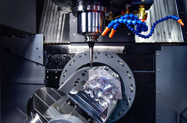
CNC Milling Machines and Axis Capabilities
The capability of CNC milling manufacturing is largely defined by the number of controllable axes and machine rigidity.
| Machine Type | Axis Configuration | Manufacturing Advantage |
|---|---|---|
| 3 Axis Milling | X / Y / Z | Cost-effective, simple geometry |
| 4 Axis Milling | + rotary axis | Multi-face machining |
| 5 Axis Milling | Simultaneous motion | Complex parts, fewer setups |
| High-Speed Milling | Optimized RPM & feed | Thin walls, aluminum |
For example, a part requiring machining on five faces may need 3–4 separate setups on a 3-axis machine, but only one setup on a 5-axis machine, reducing cumulative tolerance error and cutting lead time by 25–40%.
Advanced CNC milling manufacturing facilities choose machine configuration based on part geometry, tolerance sensitivity, and production volume, not just machine availability.
Materials Commonly Used in CNC Milling Manufacturing
Material selection directly affects machining efficiency, tool life, surface finish, and total cost.
| Material | Machinability | Typical Applications |
|---|---|---|
| Aluminum 6061 | Excellent | General structural parts |
| Aluminum 7075 | Good | Aerospace-strength components |
| Carbon Steel | Medium | Industrial machinery |
| Stainless Steel 304 | Medium–Low | Corrosion resistance |
| Stainless Steel 316 | Low | Chemical & marine |
| Brass | Excellent | Precision fittings |
| Engineering Plastics (POM, PEEK) | Excellent–Medium | Insulation & lightweight parts |
Machining stainless steel can increase cycle time by 40–60% compared to aluminum, while aluminum alloys allow higher spindle speeds and faster material removal.
A skilled CNC milling manufacturing partner evaluates performance requirements vs. machining cost, often recommending alternative materials to optimize both.
Accuracy, Tolerances, and Dimensional Control
Tolerance capability defines the real value of CNC milling manufacturing.
| Tolerance Range | Typical Use |
|---|---|
| ±0.1 mm | General industrial components |
| ±0.05 mm | Standard precision parts |
| ±0.01 mm | Mechanical interfaces |
| ±0.005 mm | High-performance systems |
Tighter tolerances require:
- Reduced feed rates
- Tool wear compensation
- Thermal stability control
- Increased inspection frequency
Over-tolerancing is a common cost driver. Manufacturers that understand functional requirements can reduce machining cost by 15–30% simply by applying tolerances only where they matter.
Surface Finish and Functional Performance
Surface finish impacts friction, wear, sealing effectiveness, and aesthetics.
| Surface Roughness (Ra) | Functional Context |
|---|---|
| Ra 3.2 μm | Structural parts |
| Ra 1.6 μm | Sliding or mating surfaces |
| Ra 0.8 μm | Precision assemblies |
| Ra 0.4 μm | High-end mechanical components |
For example, sealing grooves in CNC milling manufacturing often require Ra ≤ 1.6 μm to ensure gasket compression and leak prevention.
Surface finishing methods such as bead blasting, polishing, or anodizing are selected based on both functional and environmental requirements.
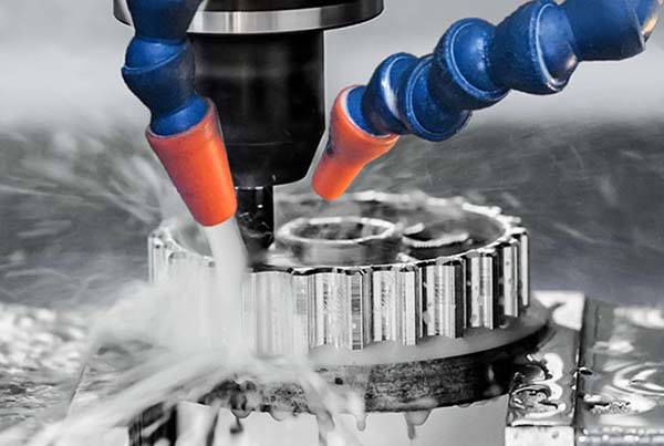
Tooling Strategy and Cutting Parameter Optimization
Tooling strategy is one of the biggest performance differentiators in CNC milling manufacturing.
Key variables include:
- Tool material (carbide, coated carbide)
- Cutter diameter and flute count
- Spindle speed (RPM)
- Feed rate and depth of cut
Using adaptive toolpaths and optimized engagement angles can extend tool life by 20–40% while maintaining consistent surface finish.
Experienced manufacturers continuously adjust parameters to balance speed, accuracy, and tool wear, rather than relying on default CAM settings.
Design for CNC Milling Manufacturing (DFM)
Good DFM reduces cost and improves consistency.
| Design Feature | Poor Design | Optimized Design |
|---|---|---|
| Internal corners | Sharp 90° | Fillets ≥ tool radius |
| Pocket depth | Excessive | ≤3× tool diameter |
| Thin walls | <1 mm | ≥1.5–2 mm |
| Hole depth | Very deep | ≤5× diameter |
Applying DFM principles early can reduce CNC milling manufacturing time by 20–35% and improve repeatability for production runs.
Production Scale: Prototype to Mass Manufacturing
CNC milling manufacturing supports a wide production range.
| Production Stage | Quantity | Manufacturing Focus |
|---|---|---|
| Prototype | 1–5 pcs | Design validation |
| Low Volume | 10–200 pcs | Process refinement |
| Medium Volume | 200–5,000 pcs | Cost optimization |
| High Volume | 5,000+ pcs | Automation & stability |
Manufacturers that invest in fixtures, standardized programs, and process documentation ensure consistency across repeated orders.
Quality Control and Inspection Systems
Reliable CNC milling manufacturing requires systematic quality control.
Common inspection tools include:
- Digital calipers and micrometers
- Height gauges
- Coordinate Measuring Machines (CMM)
- Surface roughness testers
| Inspection Stage | Purpose |
|---|---|
| First Article Inspection | Process approval |
| In-Process Inspection | Stability control |
| Final Inspection | Shipment validation |
Documented inspection ensures traceability and reduces risk in regulated industries.
How to Choose a CNC Milling Manufacturing Partner
Key evaluation factors include:
- CNC milling axis capability
- Material machining experience
- Tolerance and finish consistency
- Inspection and quality systems
- Engineering communication and DFM support
A reliable CNC milling manufacturing partner functions as an extension of the customer’s engineering team, not just a parts supplier.
Why Xavier Is a Reliable CNC Milling Manufacturing Partner
Xavier provides professional CNC milling manufacturing services with 3/4/5 Axis milling, strict tolerance control, and comprehensive inspection systems. From rapid prototypes to scalable production, Xavier focuses on functional accuracy, surface quality, and long-term manufacturing stability.
By combining engineering insight with reliable CNC capacity, Xavier helps customers reduce cost, shorten lead time, and bring complex CNC milling manufacturing projects into production with confidence.
Some of the images and text in this article are collected and compiled from the internet. If there is anything inappropriate, please contact us for processing.