
Core Knowledge Points & Themes for Milling Machining Parts
- What Milling Machining Parts Are and Where They Are Used
- CNC Milling Processes and Axis Configurations
- Material Selection for Milling Machined Parts
- Dimensional Accuracy and Tolerance Capabilities
- Surface Finish and Functional Requirements
- Tooling, Cutting Parameters, and Process Optimization
- Design for Milling (DFM) Best Practices
- Production Volume, Repeatability, and Scalability
- Quality Control and Inspection Methods
- How to Choose a Reliable Milling Machining Parts Manufacturer
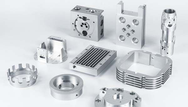
What Milling Machining Parts Are and Where They Are Used
Milling machining parts are components produced by rotary cutting tools removing material from a fixed or moving workpiece, typically using CNC milling machines. Unlike turning parts, milling parts are usually prismatic, multi-faced, or geometrically complex, often requiring machining on several planes.
Common milling machining parts include:
- Machine brackets and mounting plates
- Precision housings and casings
- Structural blocks with pockets and slots
- Heat sinks and electronic frames
- Aerospace and automation components
These parts are widely used in industries where flatness, perpendicularity, and multi-surface alignment are critical. Milling machining parts often act as structural or functional cores, meaning dimensional errors directly affect assembly accuracy.
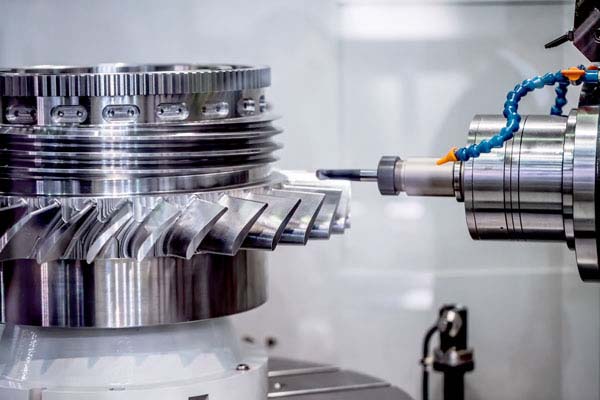
CNC Milling Processes and Axis Configurations
The complexity and cost of milling machining parts depend heavily on CNC machine configuration.
| CNC Milling Type | Axis | Typical Application |
|---|---|---|
| 3 Axis Milling | X / Y / Z | Simple prismatic parts |
| 4 Axis Milling | 3 Axis + rotation | Multi-face machining |
| 5 Axis Milling | Simultaneous motion | Complex geometry |
| High-Speed Milling | Optimized RPM/feed | Aluminum & thin walls |
For example, a part requiring machining on five faces can be completed in one setup on a 5-axis machine, compared to 3–4 setups on a 3-axis machine, reducing tolerance stack-up and cutting total cycle time by up to 25–35%.
Manufacturers with multiple axis capabilities can choose the most cost-effective process, rather than forcing all parts into a limited setup.
Material Selection for Milling Machined Parts
Material selection directly impacts tool wear, machining speed, surface quality, and cost.
| Material | Machinability | Typical Use |
|---|---|---|
| Aluminum 6061 | Excellent | Structural & lightweight |
| Aluminum 7075 | Good | High-strength aerospace |
| Carbon Steel | Medium | Industrial components |
| Stainless Steel 304 | Medium–Low | Corrosion resistance |
| Stainless Steel 316 | Low | Chemical & marine |
| Brass | Excellent | Precision fittings |
| Engineering Plastics (POM, PEEK) | Excellent–Medium | Insulating parts |
Machining stainless steel can increase cycle time by 40–60% compared to aluminum, while high-strength aluminum alloys like 7075 offer steel-like strength at reduced weight.
Experienced milling machining parts manufacturers often suggest material substitutions that meet performance requirements while lowering cost or lead time.
Dimensional Accuracy and Tolerance Capabilities
Tolerance control is a defining feature of high-quality milling machining parts.
| Tolerance Level | Application Context |
|---|---|
| ±0.1 mm | General industrial |
| ±0.05 mm | Precision assemblies |
| ±0.01 mm | Mechanical interfaces |
| ±0.005 mm | High-performance systems |
Tighter tolerances require:
- Slower feed rates
- Tool wear monitoring
- Temperature control
- Increased inspection
A good manufacturer helps customers apply functional tolerances, tightening only the features that affect fit or performance, which can reduce machining cost by 15–30%.
Surface Finish and Functional Requirements
Surface finish is not purely cosmetic. It influences friction, wear, sealing, and thermal performance.
| Surface Finish (Ra) | Typical Use |
|---|---|
| Ra 3.2 μm | General structural parts |
| Ra 1.6 μm | Sliding interfaces |
| Ra 0.8 μm | Precision assemblies |
| Ra 0.4 μm | High-end mechanical systems |
For example, sealing surfaces on milling machining parts often require Ra ≤ 1.6 μm to ensure gasket effectiveness and leak prevention.
Secondary operations such as polishing, bead blasting, or anodizing may be applied based on functional requirements.
Tooling, Cutting Parameters, and Process Optimization
Tool selection and cutting strategy significantly affect both part quality and production efficiency.
Key variables include:
- Tool material (carbide, coated carbide)
- Cutter diameter and flute count
- Spindle speed (RPM)
- Feed rate and depth of cut
Optimized toolpaths, such as adaptive clearing, can reduce cutting forces and extend tool life by 20–40%, especially in aluminum and steel milling.
Advanced milling machining parts manufacturers continuously refine parameters to balance speed, tool life, and surface quality.
Design for Milling (DFM) Best Practices
Design decisions strongly influence manufacturability and cost.
| Design Feature | Poor Practice | Optimized Practice |
|---|---|---|
| Internal corners | Sharp 90° | Fillets ≥ tool radius |
| Pocket depth | Excessive | Depth ≤ 3× tool diameter |
| Thin walls | <1 mm | ≥1.5–2 mm |
| Hole depth | Too deep | ≤5× diameter |
Applying DFM principles early can reduce machining time by 20–30% and significantly improve repeatability for batch production.
Production Volume, Repeatability, and Scalability
Milling machining parts are suitable for a wide range of production volumes.
| Volume Type | Typical Quantity | Key Focus |
|---|---|---|
| Prototype | 1–5 pcs | Design validation |
| Low Volume | 10–200 pcs | Process tuning |
| Medium Volume | 200–5,000 pcs | Cost optimization |
| High Volume | 5,000+ pcs | Automation |
Manufacturers that invest in fixtures and standardized setups can maintain consistent quality across repeated orders, making long-term supply more reliable.
Quality Control and Inspection Methods
Precision milling machining parts require systematic inspection.
Common inspection tools include:
- Digital calipers and micrometers
- Height gauges
- Coordinate Measuring Machines (CMM)
- Surface roughness testers
| Inspection Stage | Purpose |
|---|---|
| First Article Inspection | Process validation |
| In-Process Inspection | Consistency control |
| Final Inspection | Shipment approval |
Documented inspection ensures traceability and repeatability, especially for critical components.
How to Choose a Reliable Milling Machining Parts Manufacturer
Key evaluation criteria include:
- CNC milling axis capability
- Material machining experience
- Tolerance and finish capability
- Quality inspection systems
- Engineering communication and DFM support
A strong milling machining parts manufacturer acts as a manufacturing partner, not just a supplier.
Why Xavier Is a Trusted Supplier for Milling Machining Parts
Xavier specializes in precision milling machining parts, offering 3/4/5 Axis CNC milling, advanced process control, and strict quality inspection. From early-stage prototypes to scalable production, Xavier focuses on functional accuracy, surface quality, and long-term consistency.
By combining engineering insight with reliable machining capacity, Xavier helps customers reduce cost, improve performance, and bring complex milling machining parts into production with confidence.
Some of the images and text in this article are collected and compiled from the internet. If there is anything inappropriate, please contact us for processing.