Gear Manufacturing – Processes, Materials, and Applications
Gears, as core components in mechanical transmission systems, are widely used in automobiles, aviation, industrial equipment, and other fields. Through precise meshing, they transmit power from one shaft to another, achieving speed and torque conversion.
However, the gear manufacturing process is far more complex than one might imagine. From raw material selection to final precision machining, every step is crucial. This article will provide an in-depth understanding of the basics of gears and the entire gear manufacturing process.
Table of Contents
1.What is a Gear?
Gears can be simply understood as wheels with teeth. They are key components in machinery that transmit power and motion. When one gear rotates, its teeth mesh with the teeth of another gear, transmitting rotational motion and power to the other shaft. If one gear is straightened to an infinitely long tooth surface, it becomes a rack, which can convert rotational motion into linear motion.
Gear transmission has several significant advantages over other transmission methods: precise transmission, accurate angular velocity ratios, long life, and minimal energy loss. Gears are widely used, from small precision transmissions such as clocks and measuring instruments to large power transmissions such as automobiles, ships, and industrial machinery.
There are many types of gears, but the simplest and most common one is the spur gear, which is used to transmit power between two parallel shafts. Its tooth surface is parallel to the shaft, and its structure is intuitive and easy to manufacture. It is the most basic type of gear in most mechanical systems.
2.Gear types and applications
Before learning the manufacturing process of gears, it is also important to understand the various types of gears and their applications. The structure, tooth shape, and load capacity of gears vary, which directly determine their performance. Mastering this information will help you choose the most suitable gear type. If necessary, you can also consult our professional engineers for guidance. The following will introduce the six most common types of gears:
(1) Spur gears
Spur gears, also known as straight-tooth cylindrical gears, are the most common type of parallel-axis gears. Their tooth lines are parallel to the gear shaft, and their tooth surfaces are cylindrical. They have a simple structure, mature processing technology, and high manufacturing precision. Spur gears generate almost no axial force when meshing, so they have low requirements for bearings and high efficiency. They are widely used in industrial machinery, transmission devices and general power transmission systems, but they are noisy when running at high speeds.
(2) Helical gears
Helical gears are based on spur gears, but the tooth lines are twisted into a spiral along the cylinder, so that the gears gradually contact during the meshing process, running more smoothly, with low noise and high load capacity. They are suitable for high-speed or high-load occasions, such as automobile transmissions and high-speed industrial reducers.
Unlike spur gears, helical gears generate axial thrust, so they must be used with thrust bearings. Their manufacturing precision requirements are also higher, and the processing cost increases accordingly.
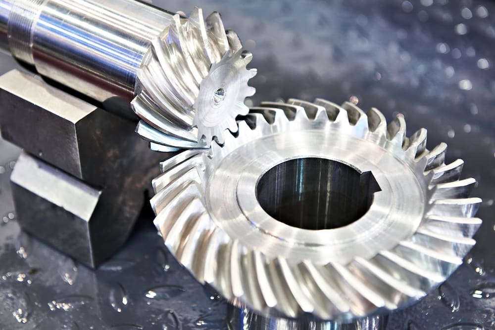
(3) Bevel gears
The tooth surface of bevel gears is located on the conical surface. They are mainly used for power transmission between two intersecting shafts. The common angle is 90°. According to the different tooth shapes, they can be divided into straight bevel gears, spiral bevel gears, hypoid gears, equal diameter bevel gears, crown gears, etc.
Straight bevel gears have a simple structure, but they are noisy when running at high speeds; spiral bevel gears have smooth meshing and high load-bearing capacity and are widely used in equipment such as automotive differentials, industrial machinery, and hand drills. Due to the complex tooth surface of bevel gears, the manufacturing process is more difficult than that of cylindrical gears, and requires high precision and processing equipment.
(4) Worm Gear
A worm gear is a non-parallel axis transmission structure consisting of a spiral worm and a worm wheel meshing. It can achieve a high reduction ratio in a single stage and has a self-locking function, that is, the worm can drive the worm wheel, but the worm wheel is difficult to reverse drive the worm, which is very important in elevators, lifting machinery, and transmission systems.
Since the worm and worm wheel are in sliding contact, the friction is large and the efficiency is relatively low. At the same time, a hard worm and a soft worm wheel are required to reduce wear. The lubrication conditions must be good to ensure long-term smooth operation.
(5) Internal Gear
The teeth of the internal gear are cut on the inner side of the gear body and are often meshed with the external gear. When meshing, the rotation direction is the same as that of the external gear. Internal gears have a high contact ratio, smooth operation and low noise, making them suitable for compact transmission systems such as planetary gear transmissions, gear couplings and compact reducers.
In manufacturing, internal gears require attention to the number of teeth and interference issues, so processing and finishing are more difficult.
(6) Racks
Racks are long strips of gears with teeth cut at equal intervals along a straight line. By meshing with a pinion, they convert rotary motion into linear motion, or vice versa.
Racks can be made into straight or helical teeth, and both ends can be processed into a spliced structure. They are used in automotive steering systems, CNC machine tools and various linear drive mechanisms.
Compared with other gears, racks require high precision in processing, especially the uniformity of tooth shape and tooth pitch, which directly affects the smoothness of movement and transmission accuracy. In general, these gears have their own characteristics in terms of definition, meshing mode and application scenarios: spur gears have a simple structure, high efficiency but high noise; helical gears have smooth operation and strong load-bearing capacity but generate axial force; bevel gears can change the transmission direction and are suitable for staggered shaft transmission; worm gears are suitable for high reduction ratios and self-locking situations; internal gears are compact and have smooth contact; and racks are used for the conversion of rotation and linear motion.
The selection of the appropriate gear type requires a combination of specific working conditions, load requirements, noise limits, and processing and manufacturing costs.
3.Which material is used for gear manufacturing?
In gear manufacturing, material selection directly affects the performance, life, processing technology and cost of gears. Commonly used materials are copper alloys, iron alloys, aluminum alloys and thermoplastics, which can meet different requirements from high-strength transmission to lightweight design.
(1) Copper alloys
Copper alloys are usually used in situations where corrosion resistance or anti-magnetic properties are required. The three most common copper alloys are brass, phosphor bronze and aluminum bronze.
- Brass is an alloy of copper and zinc with excellent machinability and antibacterial properties. Its ductility is related to the zinc content, with low-zinc brass being more flexible and high-zinc brass being harder. Due to its good machinability and smooth surface properties, brass gears are mostly used in low-load applications such as instrument drive systems or light mechanical transmissions.
- Phosphor bronze is made by adding tin and phosphorus to copper to enhance its strength, stiffness and wear resistance. It can maintain stable performance in high-friction environments and is therefore widely used in high-wear areas such as worm gears, and can resist wear and lubricant erosion caused by long-term operation.
- Aluminum bronze is an alloy containing copper, aluminum, iron, nickel and manganese with excellent wear resistance and corrosion resistance. In particular, aluminum bronze can resist corrosion from salt water and organic acids in marine or high-humidity environments. Due to its high strength and good wear resistance, it is often used in helical gears, worm gears and other gears that need to carry large loads.
(2) Ferroalloys
Ferroalloys are the most commonly used and widely used materials in gear manufacturing, especially for mechanical transmission systems that require high strength and high hardness.
- Cast iron offers excellent castability and vibration damping properties, making it suitable for gear applications with low to medium loads. However, its brittleness makes it unsuitable for high-speed or high-shock environments.
- Carbon steel is the most commonly used gear material due to its low price, good machinability, and heat-hardening properties. Depending on its carbon content, it can be categorized as low-carbon steel, medium-carbon steel, and high-carbon steel. Common applications include spur gears, helical gears, and bevel gears.
- Alloy steels incorporate elements such as chromium, nickel, molybdenum, and manganese into carbon steel, imparting increased strength, toughness, and wear resistance. After carburizing, induction hardening, or case hardening, alloy steel gears can achieve a hardness exceeding HRc 60 and are commonly used in heavy-duty transmission systems.
- Stainless steel excels in applications requiring corrosion resistance and high-temperature resistance. Common grades such as 303, 304, and 316 are widely used in food processing machinery, medical equipment, and chemical transmission systems.
- Tool steel contains elements such as cobalt, molybdenum, tungsten, and vanadium, and has extremely high wear resistance and red hardness. It is mostly used to manufacture high-precision, small-module gears or cutting tools.
(3) Aluminum alloys
Aluminum alloys are ideal materials for lightweight gears, especially for applications requiring a high strength-to-weight ratio. Its density is only one-third of that of steel, but it has good machinability and corrosion resistance.
Commonly used aluminum alloys include:
- 2024 aluminum alloy (aluminum-copper system): high strength, but average corrosion resistance.
- 6061 aluminum alloy (aluminum-magnesium-silicon system): has good corrosion resistance and weldability and is the most widely used medium-strength aluminum material.
- 7075 aluminum alloy (aluminum-zinc-magnesium system): extremely high strength, commonly used in aerospace and sports machinery gears.
Aluminum alloy gears are usually anodized or passivated to enhance surface hardness and corrosion resistance. They are often used in robots, drones, and lightweight transmission equipment.
(4) Thermoplastics
For weight-sensitive, low-noise, or self-lubricating applications, thermoplastic gears are the preferred choice.
- Polyoxymethylene (POM) is one of the most common engineering plastics, with high dimensional stability, low friction coefficient, and good self-lubricating properties. It is suitable for light-loaded components such as spur gears, helical gears, and worm gears.
- Nylon has good shock absorption and high mechanical strength, and can be reinforced with glass fiber or carbon fiber to increase rigidity. Nylon gears are suitable for home appliances, office equipment, and light machinery.
Although plastic gears cannot withstand high loads, they have significant advantages in noise control, simplified lubrication, and weight reduction.
4.Factors to Consider When Selecting Gear Materials
When selecting a gear material, several factors must be considered comprehensively:
Mechanical properties—whether they meet strength, durability, and fatigue resistance requirements.
Friction and wear resistance—Gears are subject to long-term meshing, and the coefficient of friction and wear resistance directly impact their lifespan.
Manufacturability—The material must be easily machined into precise tooth profiles to reduce costs and ensure accuracy.
Therefore, there is no single “best” gear material; instead, a balance must be considered based on the specific application scenario. Steel and cast iron are suitable for high-strength and high-power transmission, bronze is more suitable for special wear-resistant environments, stainless steel is suitable for equipment requiring high corrosion resistance, and plastic gears excel in terms of lightweight and low noise.
5.Gear Manufacturing Process
Depending on the size, load, precision requirements and production batch of the gear, the manufacturing process usually includes casting, forging, extrusion and cold drawing, powder metallurgy, blanking, and additive manufacturing (3D printing). These processes will be described in detail below.
(1) Casting
Casting is one of the earliest processes used in gear manufacturing. Its principle is to pour molten metal into a prefabricated mold and form a gear blank after cooling and solidification. The teeth are usually completed by subsequent machining.
The biggest advantage of casting is that the process is relatively simple and can produce large or complex gears in one go. It is especially suitable for gears with large diameters and relatively low precision requirements. For example, large module spur gears commonly found in mining equipment, wind turbines, and metallurgical machinery are usually cast.
Common casting methods include:
Sand casting: suitable for large-sized, low-precision gears;
Shell casting and metal mold casting: higher precision and better surface finish;
Die casting: used for batch production of small or medium-sized non-ferrous metal gears.
Although casting has the advantages of low cost and high forming freedom, the structure of cast gears often has defects such as pores and shrinkage, so they still need to be improved through machining and heat treatment.
(2) Forging
Forging is a process that applies pressure to heated metal to obtain a dense structure and excellent mechanical properties during plastic deformation. Forging is an excellent manufacturing method for gears that require high strength and high load capacity.
Forged gears are generally divided into open die forging (for large gears) and closed die forging (for small gears). Because forging can make the metal grain streamline along the tooth shape, the fatigue strength and impact resistance of the finished gear are significantly better than those of cast gears.
The disadvantage is that the equipment investment is high and the process has restrictions on size and thickness. It is generally suitable for medium and large gears with a diameter of less than 6 feet (about 1.8 meters). For complex shapes or oversized gears, the feasibility of forging will be limited.
(3) Extrusion and cold drawing
Extrusion is a process in which a heated metal blank is pressed into a die to obtain a specific cross-sectional shape. It can mass-produce bars with toothed or semi-finished shapes. The gear blank can be subsequently cut, heat treated, or machined to become a finished gear.
Cold drawing (or cold drawing) is similar to extrusion, but is performed at room temperature. This process obtains the target shape by pulling the metal blank through a die, which not only improves dimensional accuracy but also improves the mechanical properties of the metal.
The advantages of extrusion and cold drawing are high production efficiency, low material waste, and good surface quality. However, these methods are not suitable for complex three-dimensional tooth structures and are mainly used in light or medium load scenarios, such as instrument gears and micro transmission parts.
(4) Powder Metallurgy
Powder metallurgy is an advanced forming process that produces high-density, dimensional-precision gears through metal powder pressing, sintering, and post-processing. The process includes powder mixing, pressing, sintering densification, and necessary surface strengthening steps.
The biggest advantage of this process is that it can directly obtain near-net-shape gears with almost no subsequent cutting, greatly reducing processing costs. In addition, powder metallurgy gears have high material utilization, which can achieve complex shapes and mass production.
However, its disadvantages are also obvious: powder metallurgy gears have high porosity and limited load-bearing capacity, making them unsuitable for high-impact or heavy-load applications. In addition, powder metallurgy molds are expensive and are only suitable for large-scale standardized production.
(5) Punching
Punching is a process of punching out gear shapes from metal sheets using a punch press and a mold. Due to its fast forming speed and low cost, it is widely used in light-load, small-size, batch-production gear production, such as printers, office equipment, medical equipment, etc.
However, punched gears are mainly used for spur gears or simple planar structures. Due to its limited three-dimensional forming capabilities, it cannot meet the needs of high-precision transmission or high-load scenarios.
(6) Additive manufacturing (3D printing)
With the maturity of 3D printing technology, gear manufacturing has entered a new stage. By stacking metal or polymer materials layer by layer, prototype gears or small batches of customized parts can be quickly produced.
The advantages of 3D printing are:
It can manufacture complex structures and lightweight gears;
No traditional molds are required, shortening the R&D cycle;
It can be combined with CNC machining to achieve “hybrid manufacturing”.
However, the material strength and surface accuracy of additive manufacturing are still inferior to those of traditional forged and cut gears, so it is mainly used in prototype verification, special transmission structures or light load systems.
6.Gear machining technology
With the development of manufacturing technology, machining has become the core link in achieving high-precision gear production. With the help of CNC technology, it can efficiently complete the precision processing of gear blanks, molds and customized gears.
(1) Gear hobbing
Gear hobbing is one of the most widely used gear machining methods. A multi-tooth hob rotates with the gear blank, and the hob gradually cuts out the tooth shape. This method is efficient and suitable for mass production, especially for processing external gears.
(2) Forming cutting
In the forming cutting method, the tool is similar to the tooth profile, and the material is removed by the tool along the axial movement until the gear tooth profile is formed. This method can process both external gears and internal gears and has strong applicability.
(3) Broaching
Broaching uses multiple tools in series to gradually deepen the cutting and “scrape” the tooth profile from the blank. It is usually carried out parallel to the broach axis and is more commonly used for internal gears, but can also be used for external gears. Broaching is highly efficient, but the tool cost is high, and it is mostly used for large-scale standard gear machining.
(4) Milling
Milling is a method of processing single teeth one by one using a milling cutter or tool with a shape similar to the tooth profile. It is highly flexible and suitable for complex, non-standard or small-batch gears. With the help of 4-axis and 5-axis CNC, milling can complete the processing of complex tooth shapes.
7.Gear post-processing process
After the gear is cut, it needs to go through a series of post-processing steps to ensure that its performance, precision and durability meet the design requirements.
(1) Heat treatment
Heat treatment is the most critical post-processing process. By changing the metal structure through heating, heat preservation and cooling, the hardness, wear resistance and fatigue strength of the gear can be significantly improved. Common methods include carburizing, nitriding, induction heating and tempering.
(2) Surface treatment
Surface treatment is used to further enhance the surface performance of the gear. Common processes include shot peening, electroplating, polishing and phosphating, which can improve surface finish, reduce friction and wear, and enhance corrosion resistance.
8.Gear surface finishing process
Finishing can ensure the size, shape and surface finish of the gear, making the gear run more smoothly and with lower noise.
(1) Grinding
Grinding is to remove a small amount of material from the gear surface by a high-speed rotating grinding wheel to correct the tooth shape and improve dimensional accuracy. It is commonly used for spur gears and helical gears, and can achieve micron-level accuracy. It is a common process to ensure gear accuracy.
(2) Lapping
Lapping can make the gear surface smoother. The gear is used in conjunction with the grinding tool, and the abrasive liquid flows over the tooth surface. The tool and the gear rotate synchronously, slightly removing material. The surface of the gear after grinding is delicate, which can reduce friction, improve running smoothness and reduce noise.
(3) Honing
Honing is suitable for processing internal gears or multi-gear structures. The honing tool can be inserted into the gear. The tool and gear rotate synchronously, and the abrasive flows over the tooth surface. Each rotation removes a small amount of material. Honing can eliminate irregularities and minor distortions, making the gear surface smooth and the meshing precise.
In general, gear manufacturing processes include two main categories: forming and machining.
9.Gear Applications in Various Industries
Gear applications in various industries can be categorized into the following areas:
Automotive: Gears are core components of engines, transmissions, and differentials, transmitting power to the wheels for acceleration, shifting, and steering control.
Aerospace: They are used in aircraft landing gear, flight control actuators, and hydraulic pumps, precisely transmitting power in high-stress, high-speed environments to ensure flight safety.
Industrial Machinery: Lathes, CNC milling machines, and robotic systems rely on precision gears to drive spindles or transmit motion. Conveyors, presses, pumps, and other equipment rely on gearboxes to provide torque and speed.
Marine: Propulsion systems use large gearboxes to convert the high-speed rotation of engines into the low-speed, high-torque required by propellers. Durable gears are also widely used in winches and other deck machinery.
Renewable Energy: Wind turbine gearboxes accelerate the slowly rotating blades to the speed required for the generator. Turbines and auxiliary equipment in conventional power plants also use gears to transmit power.
Medical Equipment: Surgical robots, MRI, and CT scanners use gears for precise manipulation and positioning, ensuring the high-precision operation of medical equipment.
Consumer electronics and appliances: Printers use tiny gears to move paper, electric drills are equipped with gearboxes to control speed and torque, and kitchen appliances like blenders and mixers rely on gears to drive accessories.
In these applications, the manufacturing precision of gears directly impacts the efficiency, lifespan, noise level, and overall performance of the equipment.
Contact Xavier for custom gear manufacturing
When it comes to custom gear manufacturing, Xavier has years of industry experience and a professional technical team, enabling us to provide high-precision, highly reliable gear solutions tailored to our customers’ specific needs.
As an ISO-certified company, our advanced equipment and comprehensive quality management system ensure that every gear meets international quality standards. We also offer competitive pricing, ensuring customers receive excellent quality and optimal value for money. Choosing Xavier means reliable, professional, and trustworthy gear manufacturing services.
Conclusion
Gears are a key component with a long history and a wide range of applications. Large gears are often cast or forged, while complex or high-precision gears are precision machined. Tooth surface treatment (heat treatment and finishing) directly affects meshing performance and wear resistance, and hobbing remains the preferred method for most external gears. Appropriate material selection and processing are key to ensuring reliability. Learn more about how Xavier manufactures precision gears in our Gear Manufacturing Guide.
FAQ:
What is the best material for gears?
The optimal gear material depends on your application. Carbon steel is widely used in gear manufacturing due to its ease of cutting, plentiful raw material availability, and strong mechanical properties.
How do I choose a gear precision grade?
Gear precision grades are typically based on international standards such as DIN, ISO, and AGMA. Common precision grades include DIN Grade 2, ISO Grade 2, and AGMA Grade 15. Choosing the appropriate precision grade depends on the gear’s application requirements and cost.
What are common gear failures and how can they be prevented?
Common gear failures include tooth breakage, pitting, and tooth surface wear. Preventative measures include proper material selection, optimized heat treatment processes, and regular inspection and maintenance.
What are the main cutting processes for gears, and when should each be used?
The main processes include hobbing, forming/shaping, broaching, milling, and grinding. Hobbing is preferred for large-scale external gear production; broaching or shaping is often used for internal gear production; milling or 5-axis CNC machining is used for small batches or complex gear production; and grinding is used for high-precision gear production.
What are the various processes involved in gear surface finishing, and what are their uses?
Common processes include grinding (for shape correction and precision), lapping (for improved finish and noise reduction), and honing (suitable for internal gears or multi-part components, further improving meshing). These processes can correct post-heat treatment deformation and enhance meshing smoothness.
When should you choose powder metallurgy or 3D printing for gear manufacturing?
Powder metallurgy is suitable for large-scale, near-net-shape small and medium-sized gears, offering excellent cost and material utilization; however, its load-bearing capacity is limited. 3D printing is suitable for rapid prototyping, small batches, or complex lightweight structures; the finished product typically still requires post-processing or heat treatment.