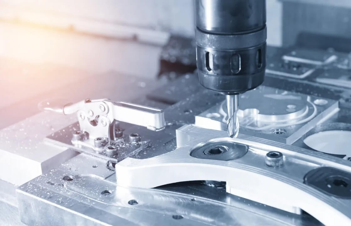
Precision Carbon Steel Machining: Material Properties and Process Optimization
Precision carbon steel machining refers to a high-precision manufacturing process that uses carbon steel (iron-carbon alloy with a carbon content of 0.05%~2.1%) as raw material and uses precision machine tools (such as high-precision CNC lathes, machining centers, etc.) to perform turning, milling, grinding and other processing to achieve part dimensional accuracy of IT5~IT7 and surface roughness Ra≤0.8μm.
The core of precision carbon steel machining is to achieve the production of parts with complex geometries and strict tolerance requirements by controlling material properties, processing technology and equipment accuracy.
Table of Contents
1.Why choose carbon steel material?
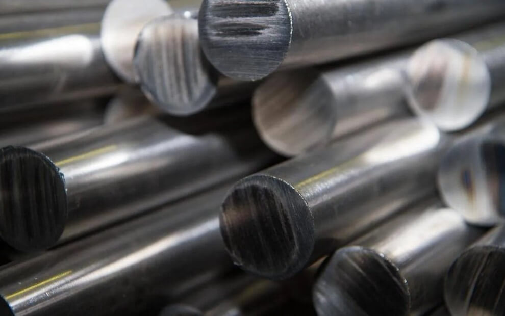
(1) Material advantage analysis
Carbon steel is mainly composed of steel, carbon, iron and other elements. The carbon content is usually as high as 2.5%, so it is often used in applications that require high durability and high strength materials. Some advantages of carbon steel are as follows:
Increased strength
Improved carburizing ability
Great for automatic lathes
Low-cost metal
100% recyclable
These qualities and machinability make CNC precision carbon steel machining parts an excellent choice for large-volume orders.
(2) Classification of carbon steel material components and their respective applications
Low carbon steel (C≤0.25%): such as Q235 and 20 steel, good plasticity and easy processing, but low strength, often used for structural parts, flanges, etc.
Medium carbon steel (0.25%<C≤0.6%): such as 45 steel and 40Cr, with balanced comprehensive mechanical properties, excellent strength and toughness after quenching and tempering, is the most commonly used material for mechanical parts (such as shafts and gears).
High carbon steel (C>0.6%): such as T8 and T10, high hardness and good wear resistance, but poor plasticity and difficult processing, mostly used for tools, molds, and springs.
(3) Mechanical properties
Strength and hardness: As the carbon content increases, the strength and hardness increase, while the plasticity and toughness decrease. For example, the hardness of 45 steel after quenching and tempering can reach HB220~250, while the hardness of T10 steel after quenching can reach HRC58~62.
Cutting performance: Low carbon steel is easy to stick to the tool, medium carbon steel has balanced cutting performance, and high carbon steel requires carbide tools or coated tools.
(4) Process performance
Weldability: Low carbon steel has good weldability, medium carbon steel requires preheating, and high carbon steel is easy to crack and requires special processes.
Heat treatment adaptability: Medium carbon steel can improve its performance through quenching and tempering and surface quenching; high carbon steel is often quenched + tempered for wear-resistant parts.
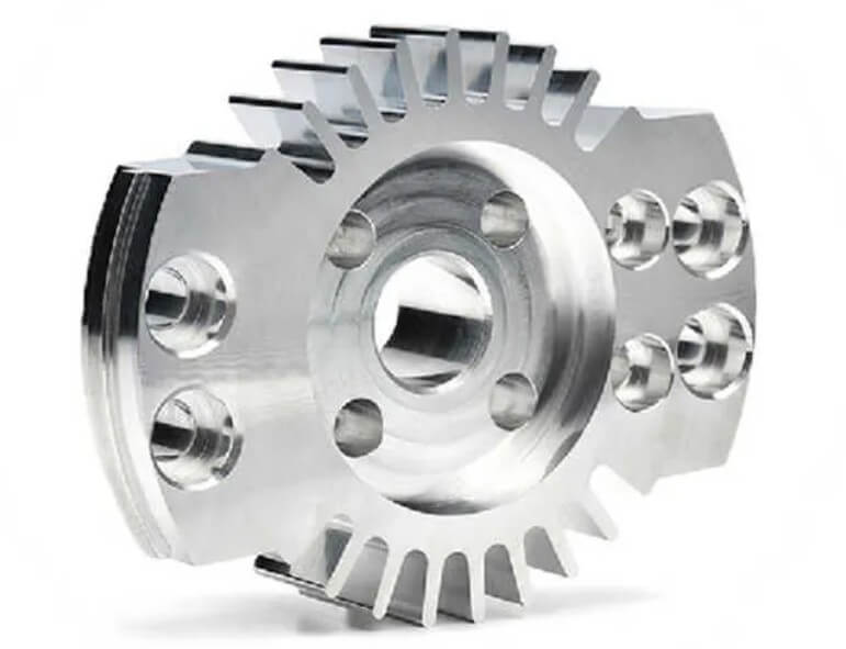
2.What are the main precision carbon steel machining parts?
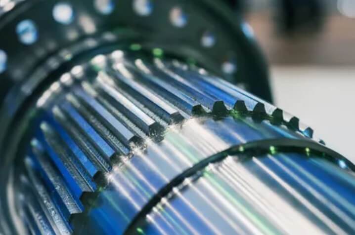
Gears and cams: require tight meshing clearance and high surface hardness.
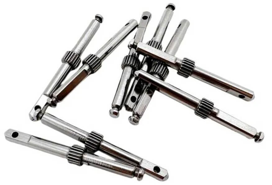
Drive shafts and spline shafts: require high rotation accuracy and fatigue resistance.
Valve body and pump body: extremely high processing accuracy requirements for complex internal flow channels and sealing surfaces.
Mold core and punch: made of high carbon steel, surface roughness Ra≤0.2 μm, high wear resistance requirements.
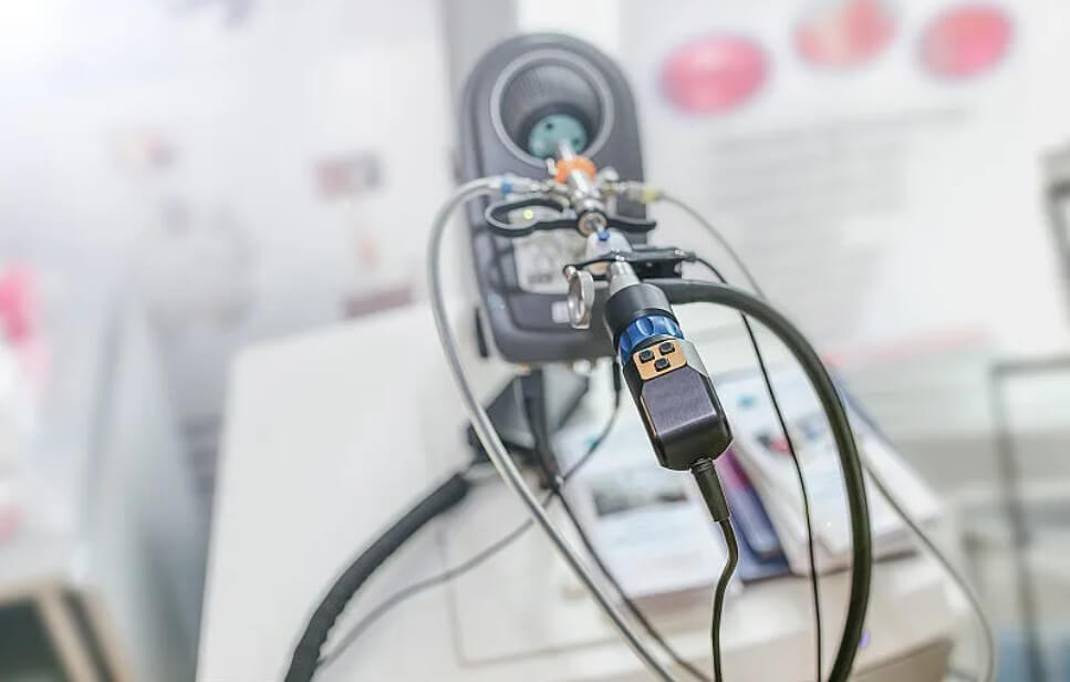
Medical device guide: burr-free, high cleanliness, commonly used in minimally invasive equipment accessories.
3.Main application areas of precision carbon steel machining
Automotive industry: high reliability parts such as engine crankshafts, gearbox gears, suspension components.
Aerospace: high fatigue life parts such as landing gear brackets and turbine shafts, which have extremely high requirements for material uniformity and surface quality.
Machine tool and mold manufacturing: injection mold cores, stamping molds, etc., have strict requirements on tolerances and surface quality.
Medical devices: surgical instruments, guide sleeves and various precision fasteners, which need to be biocompatible and burr-free.
Precision instruments: optical brackets, measuring probes, sensor housings, which have extreme requirements for shape and position tolerances and roughness.
4.Characteristics and applications of carbon steel parts
| Properties | Typical Alloys | Common Components | Typical Application Fields |
| Excellent Machinability | 12L14 (Free-Cutting Steel) | Camshafts, Worms | Commercial vehicle gearboxes, precision instrument drive systems |
| High Strength and Toughness | 45 Steel (Medium Carbon Steel) | Transmission Shafts, Gear Shafts | Machine tool spindles, agricultural machinery gearboxes |
| High Hardness and Wear Resistance | T10 (High Carbon Steel) | Punch Heads, Die Inserts | Metal stamping dies, woodworking tools |
| High Weldability and Cost-Effectiveness | Q235B (Low Carbon Steel) | Flanges, Machine Frames | Construction steel structures, storage tank supports |
| Surface Hardening and Fatigue Resistance | 20CrMnTi (Carburized Steel) | Gears, Shaft Components | Automotive gearboxes, aerospace engine drive systems |
| High Elasticity and Anti-Deformation | 65Mn (Spring Steel) | Helical Springs, Retaining Rings | Automotive suspension systems, mechanical shock-absorbing components |
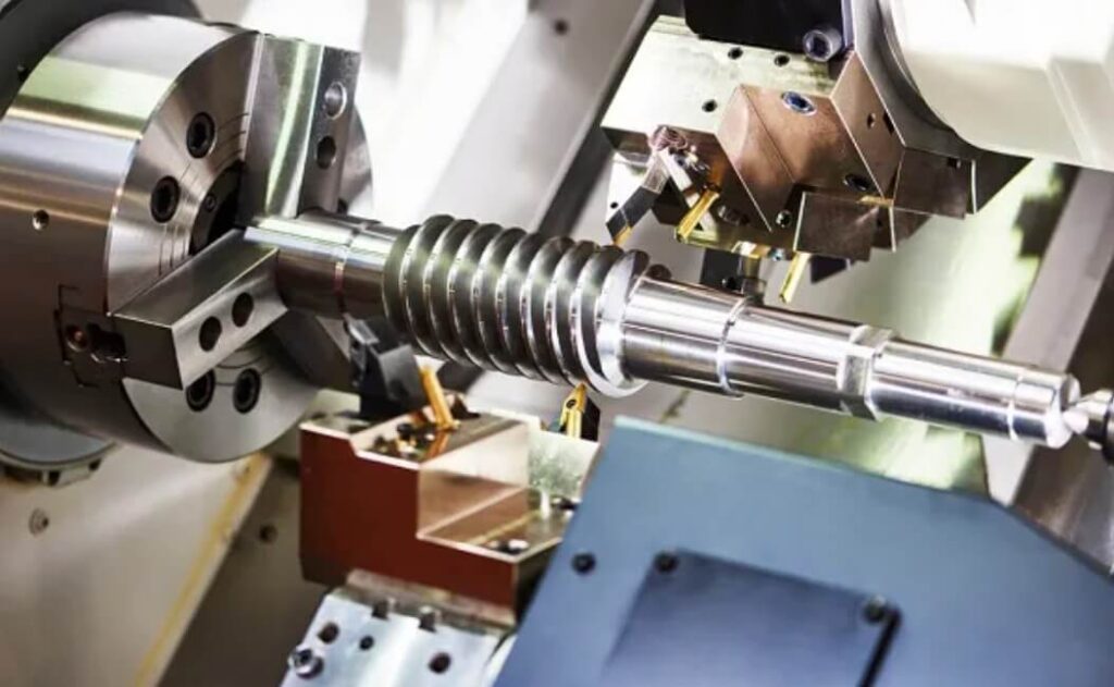
5.How to achieve precision carbon steel machining?
Common carbon steel parts (such as shafts, pins, screws, etc.) are carefully selected with high-rigidity machine tools, special fixtures and tools, partition processing strategies and online monitoring systems, combined with rough/fine turning and milling process flows, to finally achieve a stable dimensional tolerance of ±0.01 mm and a surface roughness of Ra≤0.4 μm.
(1) Machine tool and fixture selection
1) High-rigidity CNC turning and milling machine tools
Linear guides and ball screws are used, the spindle has high rigidity, and the repeat positioning accuracy can reach ±0.002 mm, which effectively suppresses long-term thermal deformation.
2) Thermal compensation system
Online measurement of the temperature of key machine tool components and dynamic compensation of the coordinate system to ensure that the all-weather processing error does not exceed ±0.01 mm.
3) Special fixtures and tooling
Customize the positioning surface and clamping mechanism according to the part geometry to prevent warping and vibration and maintain processing stability.
(2) Tool material and geometric design
1) Tool material
For rough machining, carbide is used, and for finishing, multi-layer coating (such as TiAlN, DLC) or CBN tools are used to cope with the high wear of carbon steel.
2) Geometry optimization
The front and rear tool angles and the radius of the cutting edge are precisely optimized to ensure smooth chip breakage and reduce cutting force fluctuations to stabilize the surface quality.
3) Chipbreaker and coating
The tool is equipped with a chipbreaker and sprayed with an anti-adhesion coating to ensure that the chips are not entangled and avoid surface scratches.
(3) Precision carbon steel machining process and parameter optimization
1) Partitioning strategy
Rough machining area: Use a large cutting depth (1-3 mm) and high feed to quickly remove material and leave a 0.5-1 mm margin, with efficiency as the priority.
Intermediate finishing area: The cutting depth is halved, the feed is slightly reduced, and 90% of the margin is removed to prepare for finishing.
Finishing area: cutting depth ≤ 0.5 mm, feed 0.05–0.1 mm/tooth (milling) or 0.1–0.2 mm/rev (turning), to ensure size and roughness.
2) CNC turning parameters
Cutting speed: 80–120 m/min for medium carbon steel, appropriately reduced to 50–80 m/min for hardened or high carbon steel.
Feed and cutting depth: Finishing feed 0.1–0.2 mm/rev, cutting depth 0.3–0.5 mm, completed in multiple times.
High-pressure cooling: 30–80 bar nozzle directly into the cutting area, quickly dissipate heat, reduce thermal deformation and tool wear.
3) CNC milling parameters
Spindle speed: 1500–3000 rpm (adjusted according to tool diameter and material hardness).
Feed rate: 0.1–0.3 mm/tooth for rough milling, 0.05–0.1 mm/tooth for fine milling; cutting depth 0.5–1.5 mm, tool diameter and cutting width ratio (ae/d) controlled within the range of 0.1–0.3.
Chip removal and cooling: Equipped with multi-angle chip cleaning nozzles and MQL lubrication to ensure that chip cleaning and lubrication are both efficient and environmentally friendly.
(4) Finishing and post-processing
1) Fine grinding or super-finishing
For high-demand surfaces or key mating surfaces, grinding (Ra≤0.2 μm) or super-finishing is used to eliminate tool marks and improve finish.
2) Polishing and chemical treatment
For difficult-to-grind areas such as threads and keyways, chemical polishing or electrolytic polishing can be performed to further improve surface quality.
(5) Online monitoring and quality verification
1) Multi-sensor fusion
Vibration, cutting force and temperature sensors monitor the cutting status in real time, and the parameters are fine-tuned instantly through the adaptive control system to maintain stable processing.
2) Offline/online measurement
Use coordinate measuring machine (CMM) and profiler to detect key dimensions and roughness, and combine with statistical process control (SPC) to analyze trends and conduct closed-loop optimization.
(6) Application examples
Industrial shafts and pins: mill small keyways after turning shoulders and chamfering, and then fine-grind the outer circle to achieve ±0.01 mm coaxiality and Ra≤0.3 μm.
High-precision gears and cams: rough milling contour → fine milling spline → grinding tooth surface, tooth shape error <5 μm, Ra≤0.4 μm.
Fasteners and dowel pins: turning → chamfering → thread rolling → polishing, thread tolerance 6g/6H, smooth surface without burrs.
FAQs:
Why do burrs appear after processing?
Chip adhesion is often caused by too low cutting speed, improper tool geometry or poor chip breaking. Solution: Optimize chip breaker design, increase cutting speed and combine high-pressure gas/liquid chip cleaning.
How to prevent dimensional deviation?
Strictly control machine tool thermal deformation (thermal compensation), use online measurement (CMM or trigger probe) and add compensation parameters to the tool path.
Why is the tool life short in high carbon steel machining?
High hardness and chip adhesion lead to chipping. CBN tools or high-performance coated tools should be used, and the cutting speed and cutting depth should be reduced.
How to ensure surface roughness Ra≤0.4 μm?
Use multi-pass micro-feed cutting, and finally perform fine grinding or super-finishing, and combine roughness online measurement to feedback and adjust parameters.
Which is more difficult to process, medium carbon steel or high carbon steel?
Medium carbon steel has good toughness and plasticity, and the risk of processing vibration and chipping is low; high carbon steel has high hardness and stricter requirements on tools and parameters.