How to Choose the Right Grooving Tool? CNC Lathe Grooving Guide
Grooving tools are essential tools in CNC lathe machining, used to cut precise grooves on or within workpiece surfaces. Whether it’s an external circular groove, an internal hole groove, or a face groove, different tools correspond to different applications. Only by fully understanding the characteristics and processing principles of grooving tools can you achieve efficient, stable, and precise production.
Table of Contents
1.What is CNC Grooving?
CNC grooving uses CNC lathes and grooving tools to cut straight, circular, V/U-shaped, or custom-profile grooves on the inner bore, outer surface, or end face of a workpiece. Its main purpose is to create slots for seals, O-rings, or components, and to improve assembly accuracy and positioning.
For example:
- • Cutting a small groove in a part to accommodate an O-ring or seal;
- • Cutting a groove in a part’s surface to relieve stress and facilitate chip breaking;
- • Processing a groove in a part’s end face or inner hole to facilitate assembly or positioning.
In terms of machining methods, it differs from conventional turning:
Turning involves slowly removing layers of material along the surface;
Grooving involves using a thin, specialized tool that penetrates the rotating surface of the workpiece vertically, creating a narrow groove at a specific location.
The key points of CNC grooving are:
- • Thin, sharp tools ensure accurate groove shape and dimensions;
- • Precise positioning ensures seals cannot be placed or assembly is not tight;
- • A variety of tool types are available; choose the appropriate tool based on the specific needs, such as external, internal, and end face grooves.
2.What are grooving tools? What are the types of grooving tools?
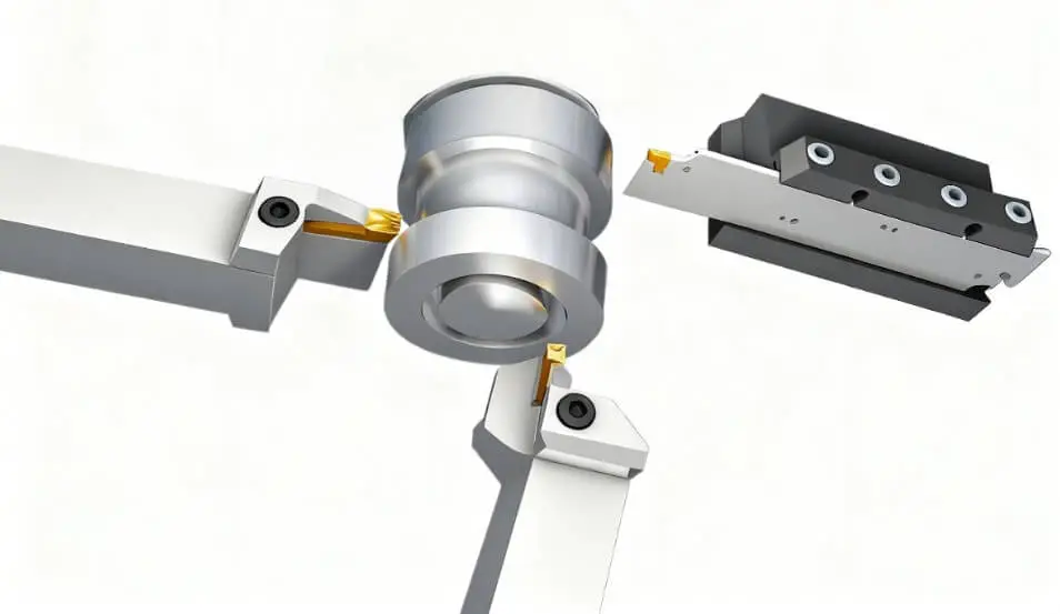
In CNC machining, there are many types of grooving tools, but there are three common core types: external, internal, and end face grooves. The main difference between them is the location of the groove.
(1) External diameter groove cutting tool
This tool is used to cut grooves on the outer surface of the workpiece. Its main function is to create the external features of metal parts. It is often used to process O-ring grooves, retaining ring grooves and some decorative grooves.
Due to the large cutting force during external groove processing, the tool needs to be strong enough. At the same time, the width and shape of the blade will be selected in different ways to meet the requirements of various groove widths and depths. During processing, if the tip of the tool is slightly lower than the center line of the workpiece, it usually has a better cutting effect.
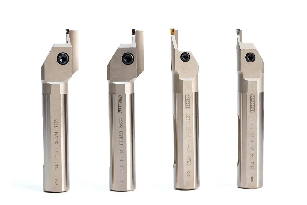
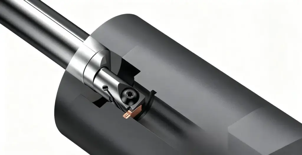
(2) Internal diameter groove cutting tool
Internal diameter groove cutting tools are specially designed for the inside of the workpiece, such as the inner wall of the pipe or the retaining ring groove, sealing groove, etc. It has a slender shape that can extend into the inside of the workpiece, but it must maintain rigidity to avoid vibration or deformation during cutting.
Due to the narrow space, the blade angle and chip discharge method are required to be higher during processing, otherwise it is easy to get stuck. Common internal groove cutting tools are made of high-speed steel, carbide, and even diamond to ensure strength and durability.
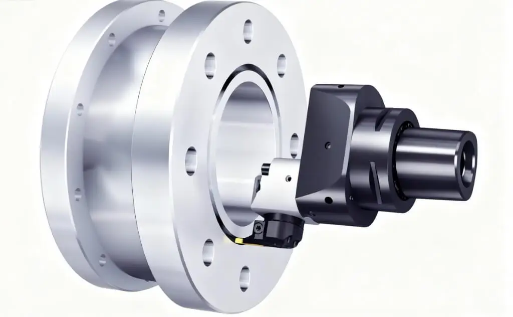
(3) End face grooving tools
End face grooving tools are used at the end of the workpiece, such as machining annular grooves on the end face of cylindrical parts. Its typical application scenarios include flanges and valve parts, which require concentric sealing grooves to be formed on the end face.
When machining the end face groove, the tool tip must be aligned with the center line of the workpiece, and the tool radius must also match the size of the groove, otherwise it will easily affect the accuracy. In order to prevent tool breakage, it is also necessary to pay attention to the timely discharge of chips.
Summary
External groove tools are responsible for the grooves on the outer surface of the workpiece, internal groove tools cut grooves deep into the workpiece, and end face groove tools are used for annular grooves at the end of the workpiece. These three types of tools almost cover common groove processing scenarios. When choosing, you mainly decide which type to use based on the groove location and workpiece structure.
3.CNC lathe grooving tool materials
When performing grooving processing on a CNC lathe, the choice of tool material directly affects the processing efficiency, surface quality and tool life.
(1) High-speed tool steel grooving tools
High-speed tool steel (HSS) is commonly used as a grooving tool material for lathes. It has good toughness and is not easy to break. It is suitable for grooving at low or medium speeds, especially for small batch or single-piece processing. Although HSS tools are not as wear-resistant as carbide, they are stable in intermittent cutting or occasional impact conditions and are an economical and reliable choice.
(2) Carbide grooving tools
Carbide is one of the most commonly used materials for lathe grooving tools. It has high hardness and wear resistance and can withstand high-speed cutting. Using carbide grooving tools can maintain a sharp blade, make the slot processing clean, and have high cutting efficiency. It is very suitable for large-scale grooving machining of various materials such as steel, stainless steel or aluminum alloy. Because carbide is relatively brittle, it is necessary to pay attention to the processing parameters when intermittent cutting or when the material hardness is uneven to avoid tool breakage.
(3) Diamond grooving tools
Diamond tools (PCD) are mainly used for high-precision grooving of non-ferrous metal materials such as aluminum alloy, copper, plastic, etc. in lathe grooving machining. Due to the extremely high hardness and excellent wear resistance of diamond, PCD grooving tools can maintain dimensional accuracy and surface finish during long processing and are suitable for precision parts processing. However, it is not suitable for processing steel materials, otherwise chemical reactions will occur, causing the tool to break.
(4) Coated grooving tools
Coated tools are improved on the basis of HSS or carbide tools. By adding a coating (such as TiN or TiAlN) on the tool surface, the wear resistance and high temperature resistance are enhanced. Coated grooving tools are suitable for processing materials such as steel, stainless steel and high-temperature alloys. They can extend tool life, improve cutting efficiency and improve slot surface quality in high-speed or continuous grooving machining. When using coated tools, it is still necessary to select appropriate parameters according to the material and cutting conditions to avoid coating shedding or tool damage.
4.How to cut a groove on a CNC lathe?
(1) Process and tool planning (CAD → CAM)
Determine the position, width, depth and tolerance of the slot in CAD; draw the chamfer or fillet radius of the slot bottom if necessary.
Generate the tool path using CAM and choose whether to divide it into multiple paths. Save in a format acceptable to the machine tool (usually post-processed G code; the design file can be saved as STEP/IGES for archiving).
(2) Select and check the tool
Select the tool according to the groove type: external groove cutter for external groove, internal groove cutter for internal groove, and end face cutter for end face groove. Confirm that the width of the blade matches the required groove width (or slightly smaller than the groove width to facilitate multiple pass stacking).
Check whether the tool material/geometry (chip breaker, radius, front and back angles) is suitable for the material being processed, and confirm that the tool clamping parts are strong and free of cracks.
(3) Workpiece clamping and positioning
Fix the workpiece on the chuck or fixture to ensure that the coaxiality and radial runout are within the allowable range. Mark and confirm the starting position of the groove.
For internal grooves, first confirm whether the hole diameter allows the tool to enter safely (shank diameter/tool head size limit).
(4) Machine tool zeroing and tool compensation setting
Return each axis of the machine tool to zero or set the work coordinate system WCS; upload G-code.
Install the tool and measure or set the tool length and tool radius offset, input the tool length and radius into the control system to ensure the accurate position relationship between the tool tip and the workpiece.
(5) Center height positioning rules
External groove (outer diameter): The tool tip is usually slightly lower than the center line of the workpiece (slightly lowered tool tip), which can improve the chip direction and cutting angle, and can be fine-tuned according to the tool geometry.
Inner groove (inner diameter): The tool tip is usually slightly higher than the center line (tool tip raised) to reduce the probability of tool breakage caused by tool tip pressure and improve the force on the tool back angle.
End face groove (surface): The tool tip should be aligned with the workpiece axis (on the center line or very close to the center) to ensure radial cutting symmetry.
(6) Program setting and parameter adjustment
Based on the material and tool, refer to the cutting parameters given by the manufacturer and set the key values such as spindle speed, feed, each cutting depth, etc. Deep grooves are preferably cut in layers to avoid cutting to the bottom in one go.
Grooving usually has a relatively stable feed and graded cutting depth. The first cutting is often set to conservative parameters to observe chips and vibration.
(7) Dry run and trial cutting
First, do a dry run. Dry run means that the tool is near the workpiece but does not touch the workpiece. The main purpose is to check the trajectory. Then do a trial cut with a smaller cutting depth to observe the cutting force, vibration, chip removal and groove shape. Fine-tune the parameters or tool height based on the results.
(8) Formal grooving
Start cutting and cut layer by layer according to the program to the target depth. Pay attention to whether the chips are discharged smoothly. When cutting the inner groove, especially make sure that the chips do not accumulate. Use appropriate cutting fluid or high-pressure chip blowing to help chip removal and cooling.
Stop immediately if vibration, chipping or abnormal chip cutting is found. Check the tool extension length, clamping and cutting parameters, and adjust them before continuing.
(9) Online detection and intermediate measurement
After the critical depth or after the processing is completed, use tools such as micrometers and internal diameter gauges to measure the groove width, groove depth and position to confirm whether they are within the tolerance range. Make compensation corrections if necessary.
(10) Finishing and surface treatment
If high precision or surface finish is required, use a smaller cutting depth and appropriate feed for the final finishing pass. After processing, deburring, cleaning, necessary heat treatment and surface treatment can be performed.
(11) Unloading, cleaning and recording
Unload the workpiece, thoroughly clean the chips and machine tool, check tool wear and record tool life and parameters for subsequent batch replication or optimization.
5.Grooving operation on lathe machine
On the lathe, “grooving” refers to the use of special tools to machine grooves on the surface of the workpiece. Depending on the position and shape of the groove, grooving can be divided into the following categories:
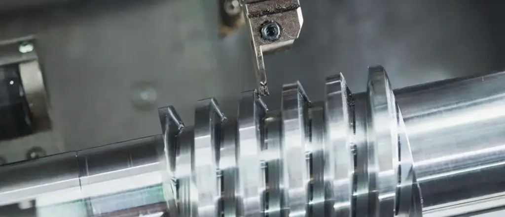
(1) Outer diameter grooving
This is the most common form of grooving, cutting a groove on the outer surface of the workpiece. For example, machining O-ring grooves, retaining ring grooves, etc. on the shaft.
There are several methods for outer grooving:
- • Single grooving: Cut a narrow groove at a time, simple and fast, suitable for shallow grooves or small batches.
- • Multi-groove machining: Cut multiple grooves on the outer diameter, which is common when the part requires multiple retaining ring positions or sealing grooves.
- • Slope grooving: The tool feeds radially while moving axially, gradually cutting out the groove shape, which is better for chip removal and less likely to wear the tool.
Features: It requires a sufficiently rigid tool and good coolant, otherwise it is easy to sharpen the tool or the groove surface will be rough.
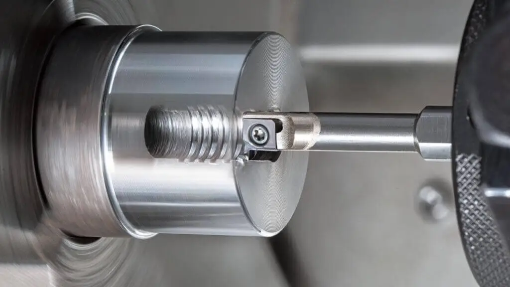
(2) Internal diameter grooving
As the name suggests, it is to cut a groove in the inner hole of the part, such as the retaining ring groove and sealing groove on the inner wall of the pipe.
- • The internal groove tool is usually slender and can be inserted into the hole, but pay attention to rigidity to avoid shaking during machining.
- • It is best to cut from the back end of the hole to the front during machining so that the chips are easily discharged.
- • Due to the narrow space, high-pressure coolant must be used to help chip removal and cooling, otherwise the tool is easy to break or the workpiece surface is scratched.
Features: It is more difficult than the external groove, the machining space is small, the tool is prone to vibration, and the tool quality and cooling requirements are very high.
(3) End face grooving
This is a concentric annular groove machined along the end face of the workpiece (the plane of a cylindrical part). It is commonly used to make sealing grooves on parts such as valves and flanges.
- • The tool must be aligned with the center line of the workpiece, otherwise the groove will be eccentric.
- • During processing, the tool must be sharp and fully cooled, otherwise burrs or rough groove surfaces are likely to occur.
- • Because the cutting force direction is special, the tool must be strong enough to avoid tool breakage.
Features: Mostly used for sealing surfaces or end assembly grooves, requiring high precision.
Table: Comparison of outer diameter grooving, inner diameter grooving, and end face grooving
(4) Straight turning grooves
This is a relatively basic type, equivalent to cutting a straight groove directly on the outer diameter or end face of the workpiece. It is different from ordinary turning in that the goal is to “cut grooves” rather than “reduce the diameter.”
- • Commonly used for simple positioning grooves or process grooves.
- • High precision, but limited cutting depth, deep grooves need to be cut in multiple times.
(5) Contour grooving
If the groove shape is complex, such as a curve or special geometry, contour grooving should be used.
- • The tool will follow the trajectory set by the CAD program and gradually process the specific shape.
- • Commonly used for customized parts, such as special-shaped sealing grooves or special structural grooves.
Features: High flexibility, but programming and tool selection are relatively complex.
6.Factors to consider when selecting a grooving tool
Several factors need to be considered when selecting the best grooving tool. The following is an overview of some of these factors:
(1) First, the type of grooving needs to be considered.
External grooves, internal grooves, and end face grooves are processed differently, and each groove type requires a specific tool design. For example, external grooves usually require a short shank, high-rigidity tool to resist lateral forces; internal grooves require a thin shank or a special internal groove cutter to enter the inner hole; and end face grooves require a face groove cutter or a special blade to ensure the stability of end face cutting.
(2) Secondly, the nature of the workpiece material needs to be considered.
The hardness, toughness and thermal conductivity of different materials vary greatly, which directly affects the choice of tool. When processing stainless steel or steel parts with high hardness, carbide or wear-resistant coating tools are usually required to ensure that the tool is not easy to wear and break; when processing softer materials such as aluminum and copper, high-speed steel or ordinary carbide tools are sufficient, while also ensuring smooth cutting and surface quality.
(3) The size and shape of the groove are also key factors.
The width and thickness of the tool must match the groove width, especially for narrow and deep grooves. The tool is prone to deflection or vibration during processing, so special tools or short shank designs are usually required to improve rigidity. If the groove has rounded corners or a specific contour, a tool with a corresponding shape must also be selected to ensure that the groove is consistent with the design.
(4) Tool material and coating are also important considerations when selecting.
The tool material determines the cutting performance and wear resistance. For example, carbide tools are suitable for high-speed cutting, while coatings (such as TiN, TiAlN) can reduce friction, reduce wear, and extend tool life, especially when processing hard materials or continuous grooving.
(5) Finally, the machine tool capacity and rigidity must also be considered.
The tool length and shank size must match the machine tool’s spindle speed, feed capacity, and fixture stability. A tool that is too long, lacks rigidity, or is mismatched with the machine tool can cause vibration, reduced machining accuracy, and even tool breakage.
7.Challenges and solutions for grooving
When grooving on a CNC lathe, although the process seems straightforward, there are actually many challenges. It is necessary to comprehensively consider the tool, machine tool and process parameters during operation.
(1) Vibration and tool chatter
When the cutting force is too large or the tool overhang is too long, the tool is prone to chatter, which not only affects the dimensional accuracy and surface finish of the slot, but may also cause the tool to break. To this end, it is necessary to select a short tool body with good rigidity or a special grooving tool to ensure that the tool is firmly clamped, and reasonably control the cutting speed and feed rate to minimize vibration.
(2) Tool wear and breakage
Tool wear and breakage are also common problems, especially when processing hard materials or continuous production. The strength and wear resistance of the tool directly affect the processing stability. Using carbide or coated tools, combined with appropriate cutting speed, feed rate and coolant, can effectively extend the tool life while ensuring the quality of the slot surface.
(3) Excessive cutting force and chip accumulation
Excessive cutting force and chip accumulation can also cause problems during the processing process. Excessive cutting force will not only accelerate tool wear, but also cause rough groove walls; chip accumulation may jam the tool or scratch the workpiece surface. The solution is to select the appropriate tool geometry angle according to the groove width and depth, reasonably adjust the feed speed and cutting depth, and use coolant or aerosol to remove chips in time.
(4) High temperature problem
The high temperature problem is particularly obvious in high-speed or long-time cutting. Excessive cutting temperature will accelerate tool wear and even cause burns on the workpiece surface. By using water-based or oil-based coolants, the processing temperature can be reduced and the tool lubrication conditions can be improved, thereby improving surface finish and processing stability.
(5) Dimensional accuracy and surface quality
Dimensional accuracy and surface quality are often the key assessment indicators of grooving. When processing deep or narrow grooves, if the tool is offset, the cutting force is uneven, or the measurement is inaccurate, it is difficult to meet the design requirements. The coping strategy is to use precise measuring tools (such as vernier calipers, feeler gauges, micrometers), keep the tool sharp, and select the matching tool width and shape according to the groove type, while adjusting the machine tool parameters to ensure processing stability.
(6) Unstable workpiece fixation or improper cutting parameters
Finally, unstable workpiece fixation or improper cutting parameters will also affect the processing effect, and even cause the workpiece to bend, deform, or the tool to break. In production, it is important to ensure that the workpiece is firmly clamped, select a reasonable cutting depth and feed speed, avoid excessive cutting force, and check the operating status of the machine tool before processing.
8.Application of grooving machining
(1) Parts that require sealing functions
Parts such as hydraulic cylinders, air cylinders, valves, and pump bodies often require sealing grooves to be machined on the inner hole or outer surface to place O-rings, rubber rings, or metal sealing rings. The purpose of this is to ensure that the parts can still maintain a tight fit under high pressure or high temperature to prevent liquid or gas leakage.
(2) Parts that require retaining rings or circlips to fix
Parts such as shafts, sleeves, and gears often have retaining ring grooves or retaining ring grooves to install retaining rings to prevent the parts from moving axially during operation. This is actually a common mechanical anti-loosening measure that can ensure the stable position of the parts during operation.
(3) Parts requiring thread relief grooves
Threaded parts such as screws, bolts, and valve stems usually have a small groove at the end of the thread, which is called a relief groove. Its function is to allow the nut or mating part to be smoothly screwed to the bottom shoulder without getting stuck due to residual cuts or incomplete threads.
(4) Transmission and positioning parts
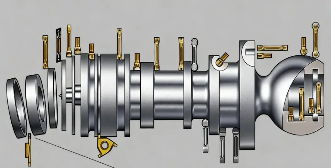
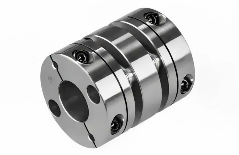
Pulleys, couplings, and keyway parts require grooving to install keys or inserts so that torque can be transmitted reliably and they also play a role in precise positioning. The processing quality of the slot often directly determines the efficiency and stability of the transmission.
(5) Parts for special industries
In the aerospace field, grooving on engine parts can not only reduce weight, but also be used to optimize aerodynamic performance or facilitate component assembly.
In medical devices and implants, tiny slot structures can help parts better fix, guide, or improve compatibility.
In electronic products, grooving of housings and connectors is often for a tighter fit and can also play a role in heat dissipation or reinforcement.
9. Summary
Grooving on a CNC lathe requires both tool selection and machining methods. Only by combining these two methods can we ensure part precision, surface quality, and production efficiency. As a professional parts manufacturer, Xavier not only handles a wide range of grooving tasks but also optimizes process routes to meet your needs. Want to achieve the ideal result for your parts? Contact us today for a customized grooving solution.

FAQ:
What are the types of grooving tools?
Common types include OD grooving tools, ID grooving tools, and face grooving tools. In addition to these three most common types, there are also specialized tools designed for specialized groove shapes, such as those with radiused corners and complex contours.
What are the types of grooving operations?
Main types include OD grooving, ID grooving, and face grooving. Furthermore, based on the direction of tool movement, grooving can be categorized as radial grooving, axial grooving, angular grooving, and contour grooving for specific shapes.
What should I pay attention to when setting up and clamping grooving tools?
Ensure the tool center height is correct, tool overhang is minimized, clamping is secure, and coolant is used appropriately to ensure smooth chip evacuation and tool life.
What cutting parameters are most critical in grooving operations?
These are primarily depth of cut, feed, and speed. Deep grooving typically requires multiple cuts. Feed should be moderate to avoid vibration, and speed should be adjusted appropriately based on the material and tool type.
What are the specific requirements for grooving tools for different materials?
Steel requires tools with high strength and wear resistance, aluminum alloys require sharp tools with good chip evacuation, stainless steel prioritizes high-temperature resistance and anti-sticking properties for grooving tools, and high-hardness materials require coatings or diamond tools.
What is the difference between grooving tools and parting tools?
Parting tools are typically thinner and used to separate workpieces; grooving tools, which need to withstand lateral forces, have wider blades. Furthermore, the chip evacuation designs of these two types of blades are different, making them inappropriate for direct interchange.
What is the difference between grooving and turning?
Turning is a machining process in which a part rotates while the tool is stationary. It is primarily used to machine cylindrical or conical workpieces. Grooving, on the other hand, involves cutting narrow grooves into the surface of a part. While grooving is sometimes performed during turning, it generally requires specialized tools and techniques.
What is the difference between a slot and a groove?
A slot is typically a narrow, elongated cut in a part, often used to hold screws, keys, or other accessories. A groove, on the other hand, is a depression or cut in a part’s surface, primarily used to aid assembly or enhance the part’s functionality.
What is the difference between grinding and grooving?
Grinding is a finishing process in which a grinding wheel is used to smooth the surface of a workpiece to ensure dimensional accuracy or improve surface quality. Grooving, on the other hand, is a cutting operation used to create a groove or groove of a specific shape in a part to achieve a desired function.
Can CNC milling machines produce internal grooves?
Yes, with the correct tools, CNC milling can also produce internal grooves in a variety of materials.