- Quick Support Form
- [email protected]
- Live Support Chat
Understanding CNC Machining Tolerances
Maximize part quality, reduce costs, and optimize designs using standardized tolerances on machined parts.
The concepts of part interchangeability and dimensional tolerances have become an accepted part of the manufacturing world. But misuse can cause many problems. For example, tolerances that are too tight may require a secondary grinding or EDM operation on the part to be completed, unnecessarily increasing costs and lead times. Tolerances that are “too loose” or do not match the tolerances of mating parts can render the assembly impossible, result in the need for rework, or in the worst case scenario, render the finished product unusable.
To help avoid tolerance overuse, this design tip includes some guidance on how to properly apply part tolerances in Xavier, as well as definitions of some of the more commonly used annotations.
Standardized Tolerances for CNC Machining
Our production services can help you achieve the tightest tolerances required for non-standard custom CNC machined parts.
*Please clearly indicate tolerances for nominal sizes below 0.5mm on your technical drawing.
Depending on the part geometry and material, we can usually achieve higher accuracy as long as you let us know your requirements. For these and other exceptions, please be sure to note this in the part design when uploading the file for a quote.
Also, please note that these are bilateral tolerances. If expressed in one-sided terms, standard tolerances will appear as +0.000/- 0.010 mm (or +0.010/- 0.000 mm).
All of these are acceptable, just like metric values, as long as you specify them in your design. To avoid confusion, stick to the “three-digit” dimensions and tolerances shown and avoid extra zeros in 1.0000 or 0.2500 inches unless there is a significant reason to do so.
Geometric dimensions and tolerances
This is another consideration. As mentioned before, we can accept GD&T tolerances. This provides a deeper level of quality control, including relationships between various part features as well as shape and fit qualifiers. Here are some of the more common ones:
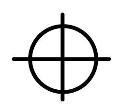
- True Location: In the bracket example cited earlier, we plotted the hole location by specifying the X and Y distances and their allowable deviation from a pair of vertical part edges. In GD&T, the location of the hole will be determined from its true location in a set of reference datums, with the qualifier MMC (Maximum Material Condition) or LMC (Minimum Material Condition).
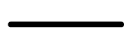
- Flatness: Milled surfaces are generally very flat, but some warping may occur once the part is removed from the machine due to internal material stresses or clamping forces during machining, especially on thin-walled parts and plastic parts. The GD&T flatness tolerance controls this by defining two parallel planes in which the milled surface must lie.
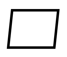
- Cylindricity: For the same reason that most milled surfaces are very flat and most holes are very round, the same goes for turned surfaces. Manufacturers use cylindricity, defined as two concentric cylinders within which the machined hole must lie, to eliminate this unlikely scenario.
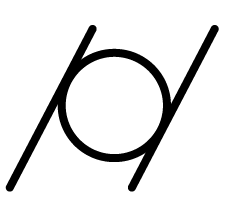
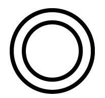
- Concentricity: The rings on the bullseye are concentric, just like the wheels on a car are concentric with the axle. If a drilled or reamed hole must exactly fit a coaxial counterbore or circular boss, concentricity callouts are the best way to ensure this.
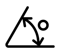
- Verticality: As the name suggests, verticality determines the maximum deviation of a horizontal machined surface from a nearby vertical surface. It can also be used to control the perpendicularity of the turning shoulder to the adjacent diameter or center axis of the part.
There are other considerations for GD&T including parallelism, straightness, contours and angles, however, as with any other non-standard tolerances, they must be noted in the design at the time of upload.