- Quick Support Form
- [email protected]
- Live Support Chat
Threading Considerations for CNC Machining
How to design threads for machined parts to help you reduce thread machining costs
External vs. Internal Threading
This is pretty basic, but important. An easy way to remember this difference is that you’ll find external threading on screws and bolts—it’s external to the hardware. Internal threads reside inside the main part. They accept, and lock in, screw and bolt threads. You’ll find more details on external and internal threading later in this design tip.
Bolt spacing
Threads on bolts and screws, it’s not a one-size-fits-all situation. In addition to metric threads, the Uniform Thread range includes three main types of imperial threads.
- UNC (coarse thread): 20 threads per inch (tpi)
- UNF (fine pitch): 28 tpi
- UNEF (ultra fine pitch): 32 tpi
Please note that adding UNEF pitch requires our precision machining services and can be noted on the drawing. For example, if you want to go with a #4-40 screw, you know that a #4 screw with a thread diameter of 0.11 inches (2.794 mm) has 40 threads per inch, which means an extra-fine pitch.
Threaded hole location
In fact, threads can be placed almost anywhere suitable for the needs of turned or milled parts and assemblies. As long as our equipment can machine the area, you can place it, but if there are obstacles, our design sub-engineer will let you know that machining is not possible at that location.
Although there don’t seem to be many placement restrictions when it comes to threads, the depth of the internal threads is an important factor to consider. If the thread depth exceeds the maximum depth of the tool, we may have to drill through both sides of the hole to complete the process. When this happens, it’s important to know whether your design will be continuous from one end to the other, but we’ll discuss some options in the next section.
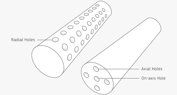
For turned parts, three types of holes can be used to accommodate internal threads:
Internal Threads
Internal threads are machined using a single-lip threading tool rather than a traditional threading tap. For parts with internal bore features that require threading, the pilot diameter needs to be left open. Our application engineers identify threaded holes when:
It falls within the diameter range of the required thread, and,
on one of the three basic axes of milling, or,
Turning perpendicular to the axis of rotation
Xavier supports machining right-hand threaded holes on parts for UNC and UNF threads ranging from #2 to 1/2-inch metric threads ranging from M2 to M12. Manufacturing methods may limit certain thread specifications.
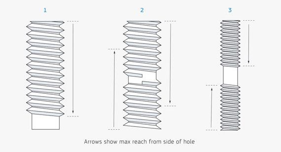
When machining an internally threaded hole, the hole may be longer than our threading tools can reach. In this case, you have several options depending on your needs:
- For long through holes that exceed the maximum reach, select the hole from the side where you expect to start driving in the screw (see Figure 1 in the three-panel diagram above). If your screw needs to go all the way through the part, you’ll also have to put the tap through the hole (in a secondary operation) to do it.
- You can also select both sides of the feature to be threaded (see Figure 2 above), but be aware of the maximum thread depth as they overlap each other in the hole. This raises concerns about threading features from both sides, as there is a risk of cross-threading and the screw may not pass completely cleanly through the part. Selecting threads from both sides is usually fine as long as the threads do not intersect (see Figure 3).
An important consideration has to do with the various diameters involved in creating threads. You must consider three measures: the primary (wide) thread, the secondary (narrow) thread, and the diameter of the pilot hole into which the thread feature will enter.
If your design instructs the manufacturer to mill a pilot hole that is the same diameter as the main (wider) threads, the hardware you use will never fit properly in that hole. Also, the screw may spin endlessly in the hole. This may not be functionally acceptable or consistent with your design.
External Threads
The advantage of external threads on turned parts is that as long as your part is suitable for turning, the threads can extend the length of the part. We use a custom thread tool that allows us to select the thread size, depth, and location within the part geometry. However, our advanced turning process provides external threads on the centerline of the part, and internal bores can be threaded as long as similar guidelines to milling are followed.
We offer external threads for on-shaft holes, axial holes and radial holes. Milling external threads is done in two stages. The first set of threads goes around half of the turned part, then the threads are milled on the other side. The two sides meet along the centerline of the part. This process works for 1/2-inch threads, but we recommend milling the threads to remove excess material or eliminate mismatches in the threads.
Smaller external threads (such as #6-32) are more difficult to machine with a ball or flat nose mill because the pitch is too tight, leaving a large radius at the root of the thread. You will need to mill the threads using a thread cutting die to remove the remaining material. On many parts, a radius of 0.008 in. (0.2032 mm) to 0.016 in. (0.4064 mm) is left.
Just like internal threads, external thread design requires the thread to be removed from the CAD model in order for our software to recognize it. Also, model milled external threads; do not model turns on them. Once you receive your turning quote, you will be able to select the appropriate thread size.